English 19
9 Final completion work
1) Disconnect the mains plug
2) Check that all parts of the unit are correctly and firmly
connected.
3) Visually inspect the charger for correct installation of
the components.
4) Fit the housing rear panel onto the bottom 3 screws
5) Make the PE wire connection between housing and
rear panel
6) Screw the rear panel tight (a total of 11 screws).
A high-voltage and PE wire test in
accordance with VDE0700 / IEC 335-1 must
be conducted after repair.
A function test must be conducted after
repair.
10 Function test
Check the following points before final assembly of the
unit:
Charging mode (mains switch in position 1)
The function test is conducted in charging mode with the
option board withdrawn and with test circuit A. The
charging current or the charging voltage can be set with
the variable measuring shunt. The components for setting
the set values are located in the module slot of the option
board.
U characteristic: U
B
= 14.4 V 0.1 V at I
L
= 5 A
I characteristic: I
L
= 30 A at U
B
= 12 V
Back-up mode (Mains switch in position 2):
The function test in back-up mode is conducted with the
option board. The battery-type selector switch must be
set to the position for maintenance-free batteries (bottom
position).
Remove the measuring circuit !
The green LED must light if the charger is switched on
with the terminals disconnected. The yellow LED must
light if the battery charging terminals are shorted.
U
B
(open circuit): 13.8 V
I
L
(short circuit): max. 3 A
If the required functions and set values are not reached in
back-up mode, there is probably a defect on the option
board. The option board must then be exchanged.
11 Final assembly
1) Disconnect the mains plug
2) Connect the fan
The fan terminals are located on the terminal strip
X10 (, terminals 7 and 8).
3) Connect the PE wire terminal of the fan in the charger
4) Screw on the housing upper section.
The screws (6 ea. in total) are located on the sides of
the housing.
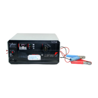
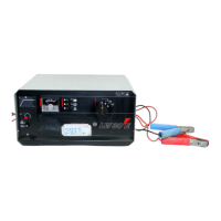
12 Illustrations and circuit diagram
The illustrations and the circuit diagram are
located at the end of these instructions
A Ammeter 1
X10 Option board 2
G1 Rectifier 3
T1 Main transformer 4
F1 Mains fuse 5
Base plate 6
V1 Regulating transistor 7
T2 Supply transformer 8
C1 Capacitor 9
RFI suppression 10
R100 Shunt 11
S1a Mains switch (mode selector switch) 12
X11 Regulator board
 Loading...