12
DISASSEMBLY/ASSEMBLY PROCEDURES
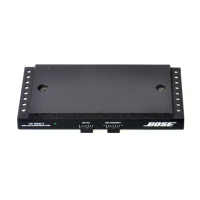
1. Bottom Cover Removal
1.1 Remove the four screws located at the
back (connector end) of the unit and the
two screws located at the front of the unit.
1.2 Remove the bottom cover.
2. Bottom Cover Replacement
2.1 Place the bottom cover onto the unit.
2.2 Secure the cover to the heatsink.
3. PCB Removal
3.1 Perform procedure 1.
3.2 Remove the plastic insulator from the
PCB.
3.3 Remove the four screws securing the
PCB to the heat sink.
3.4 Lift the PCB assembly off of the heat
sink.
4. PCB Replacement
4.1 Place the PCB assembly onto the heat
sink.
Note: Make sure that the output transistor's
insulator is in its proper position and is not
misaligned.
4.2 Secure the PCB to the heat sink.
4.3 Perform procedure 2.
1201 Disassembly/Assembly Procedure
 Loading...