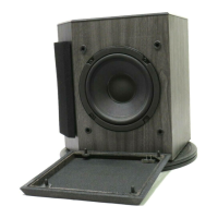
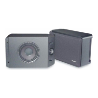
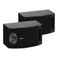
Figure 5. Model 203 Loudspeaker Crossover Assembly layout diagram
(2X)
(4X)
M
M
L1
PTC2
C1
DS1,
DS2
PTC1
FOIL
TAPE
1
2
3
4
5
6
7 8 9 10
11 12
RED
YELLOW
BLUE
BLACK
GREEN
BLUE
Model 203™ Loudspeaker Crossover Assembly part list (per figure 5)
8
Item
Number
Reference
Designator
Description Part Number Qty
1 C1 Cap, El, BP, 85, 50V, 20%, 10 uF 290391-100 1
2 PTC2 Polyswitch, 60V, 4mm 190348-040 1
3 PTC1 Polyswitch, 50V, 4mm 190348-090 1
4 Tape, Foil, w/liner 134636 1
5 DS1, DS2 Lamp. 2.5, 24Vdc, Mini 132111 2
6 PCB, Bare Board, 203 Crossover 291226-001 1
7 L1 Inductor, 65 uH, 11 Ohm Ferrite 189799 1
8 Screw, Machine, 4-40x1, Pan, Xrec 103146-16 1
9 Washer, Flat, .141,#5 108258-05 1
10 Nut, Hex, 4-40 103234-440 1
11 Screw, Tapp, .8-11x.625, Pan, XRC/S 289388-010 4
12 Foot, .25X.50, Black 174402-01 4

 Loading...
