3
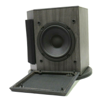
251 Environmental Speaker 256033
DISASSEMBLY/ASSEMBLY PROCEDURES
9.2 Remove the four screws (12) that secure
the Twiddler panel (15) to the baffle. Pry off
the panel.
9.3 Cut the wires as close as possible to the
terminals of the capacitor (4).
10. Crossover Capacitor Replacement
10.1 Connect the leads of the capacitor (4) to
the wires and solder the connections. The
capacitor is wired in series with the woofer’s
(1) negative terminal and the Twiddler’s (2)
positive terminal. Refer to Figure 1.
10.2 To prevent air leaks, replace the Twiddler
panel (15) and gasket (9). Line up the
Twiddler panel (15) with the cabinet and
replace the four screws (12) that secure it to
the baffle.
(Refer to Figure 4)
4.2 Line up the Twiddler™ in the cabinet and
replace the four screws (12) that secure the
Twiddler in place.
5. Woofer Removal
5.1 Perform procedure 1.
5.2 Cut the wires as close as possible to the
woofer’s (1) wire terminal.
5.3 Remove the four screws (12) that secure
the woofer to the baffle. Lift the woofer out.
6. Woofer Replacement
6.1 To prevent air leaks, apply a new gasket
(11) to the woofer. Line up the woofer (1) in
the baffle so that the wire terminal is facing
toward the Twiddlers (2). Replace the four
screws (12) that secure the woofer to the
baffle.
6.2 Attach the green and black wires to the
negative terminal and the red and yellow
wires to the positive terminal of the woofer.
6.3 Place the foam tape gasket (10) around
the edge of the baffle’s woofer mount where it
contacts the cabinet.
7. Protection Circuit Removal
7.1 Perform procedure 1.
7.2 Cut the wires as close as possible to the
leads of the polyswitch (3).
8. Protection Circuit Replacement
8.1 Connect the leads of the polyswitch (3) to
the wires and solder the connections. The
polyswitch is wired in series with the
speaker’s positive terminal and the woofer’s
(1) positive terminal. Refer to Figure 2.
9. Crossover Capacitor Removal
9.1 Perform procedure 1.
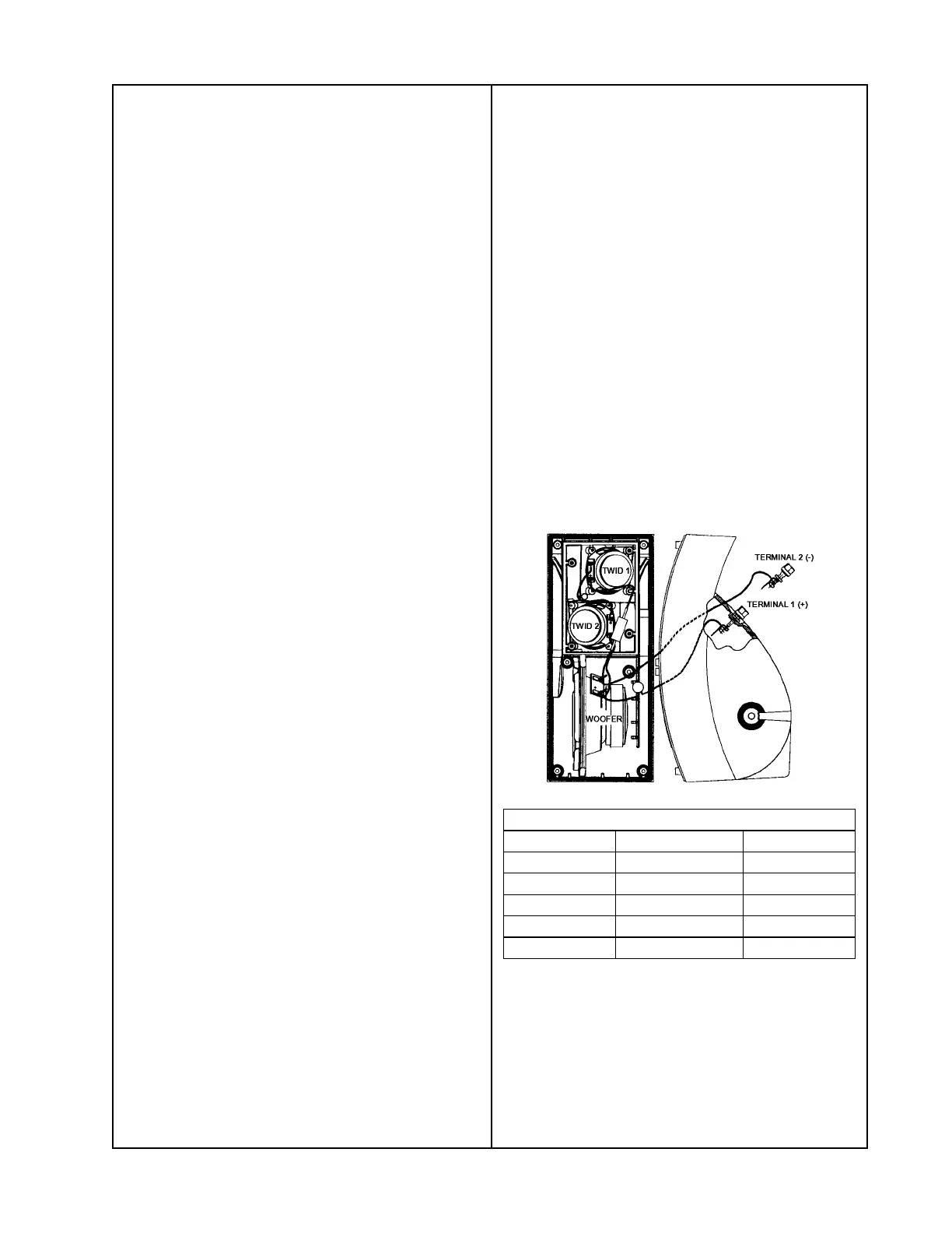
Figure 1. Wiring Diagram
Wiring Diagram Table
From To Wire
Twid 1 (-) Twid 2 (+) Gray
Twid 1 (+) Woofer (-) Black
Twid 2 (-) Woofer (+) Red
Woofer (+) Terminal 1 (+) Yellow
Woofer (-) Terminal 2 (-) Green
 Loading...