3
INSTALLATION (CONT.)
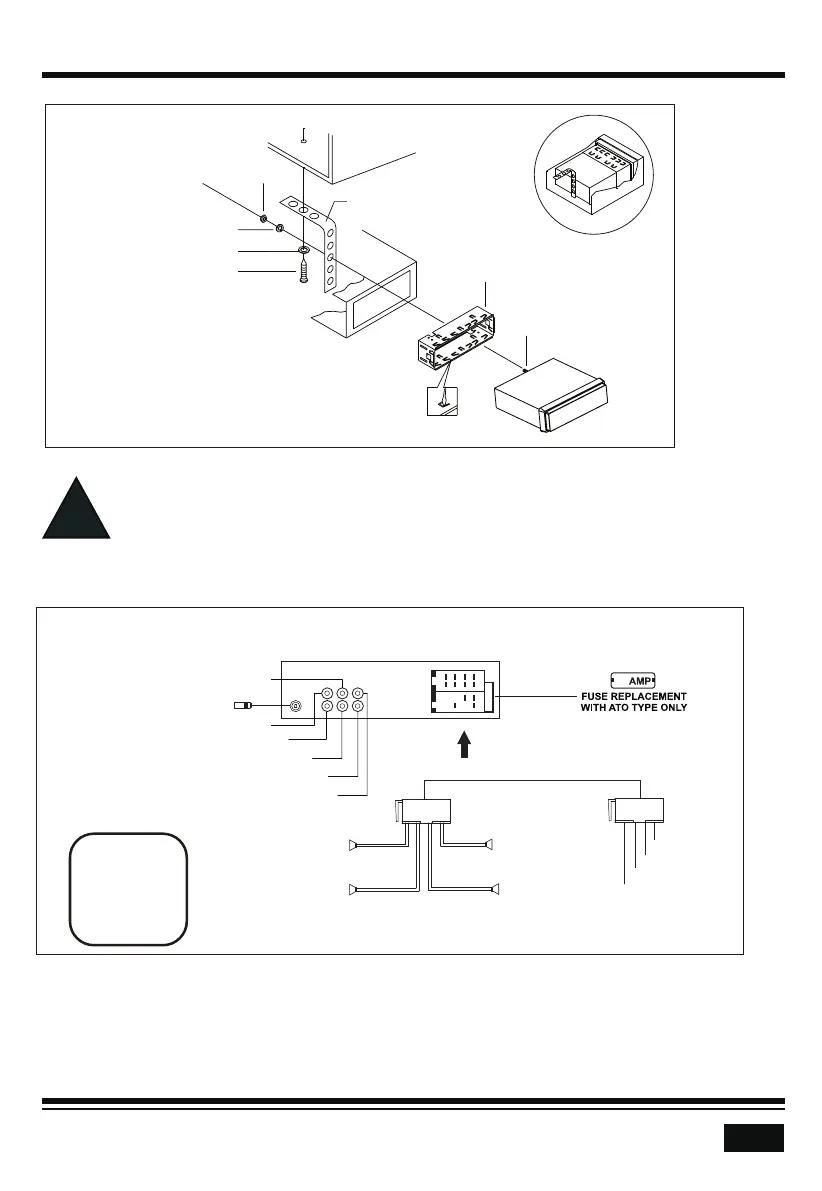
INSTALLATION
DIAGRAM
- Only use speakers with 4 ohms impedance.
- Do not attach the control panel to the chassis before wiring is complete.
- The maximum current of the auto antenna is 200mA.
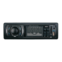
Wiring Connections
WIRING
DIAGRAM
CAUTION
+12V DC
NEGATIVE
GROUND
Removal of the Main Unit
1. Remove the metal strap from the main unit.
2. Remove the plastic trim out from the main unit.
3. Insert a bracket key into the left and right side of the main unit and draw the unit out of
the mounting sleeve.
15
White:Front Left CH RCA Output
White: Rear Left CH RCA Output
Red: Front Right CH RCA Output
AUX-Left input
AUX-Right input
Red: Rear Right CH RCA Output
Radio Antenna
15A
Purple +
Rear Left Speaker
Front Left Speaker
White +
Green +
Green/Black -
White/Black -Gray/Black -
Gray +
Front Right Speaker
Purple/Black -
Rear Right Speaker
ACC + (Red)
GND - (Black)
ANT + (Blue)
Power B + (Yellow)
HEX BOLT
SPRING WASHER
PLAIN WASHER
TAPPING SCREW
HEX NUT
DASH BOARD
METAL MOUNTING STRAP
CONSOLE
MOUNTING SLEEVE