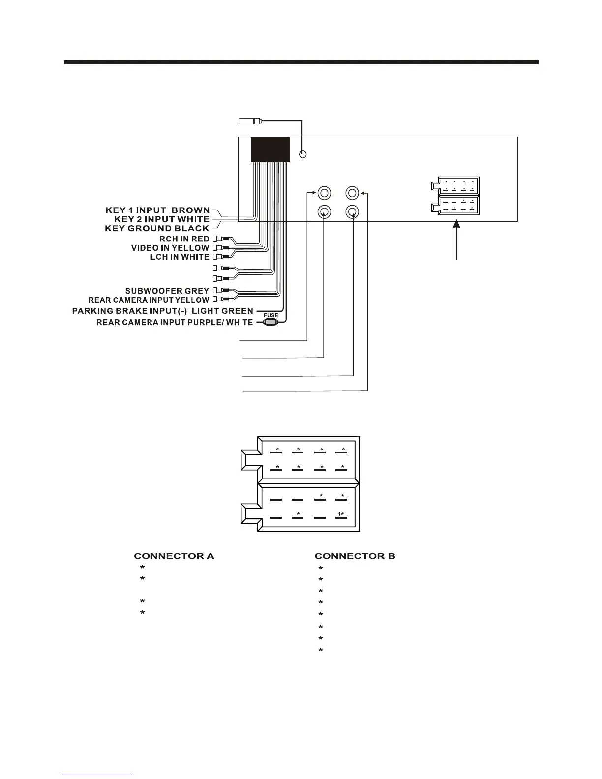
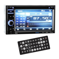
Electric Connection
WIRING CONNECTION
Note:
the ground connection cable (parking brake B-) must be connected in order for
pictures to be played back to the monitor. If the cable has not been correctly
connected, appears on the monitor. warning message
ISO CONNECTOR
1 BLACK.........................GROUND
5 YELLOW...............CONSTANT(+)
2 RED.........................IGNITION(+)
4 BLUE................AUTO ANTENNA
1 GREEN/BLACK................LEFT REAR(-)
3 WHITE/BLACK...............LEFT FRONT(-)
5 GRAY/BLACK..............RIGHT FRONT(-)
7 VIOLET/BLACK.............RIGHT REAR(-)
2 GREEN...........................LEFT REAR(+)
4 WHITE..........................LEFT FRONT(+)
6 GRAY..........................RIGHT FRONT(+)
8 VIOLET.........................RIGHT REAR(+)
5
2
4
8 6 4 2
7 5 3 1
B
A
RADIO ANTENNA JACK
FRONT RCA AUDIO OUT SOCKET
FRONT RCA AUDIO OUT SOCKET
VIDEO OUTPUT SOCKET
VIDEO OUTPUT SOCKET
White Yellow
Yellow
Red
ISO CONNECTOR
5
24
8 6 4 2
7 5 3 1
B
A
REAR RCA AUDIO OUTPUT RED
REAR RCA AUDIO OUTPUT WHITE