EasyManua.ls Logo

Boss Dr. Rhytm DR-550 MK II User Manual

Boss Dr. Rhytm DR-550 MK II
13 pages
To Next Page IconTo Next Page
Page #1 background imageLoading...
Page #1 background image
APRIL.1992
DR-550mk2
obqss
DR-550
MK
n
Dr
Rhythm
ERRATA
&
SUPPLEMENT i
s
attached at
the
end of
the
page, it
DDDDDDDDDDDDDDDDDD
TABLE OF
CONTENTS
Page
SPECIFICATIONS
1
EXPLODED
VIEW
2
DR-550mk2
DISASSEMBLY
PROCEDURE
DR
550m
k2
/
}£.&
3
AND
PRECAUTIONS
PARTS LIST
BLOCK
DIAGRAM
CIRCUIT
DESCRIPTION
CIRCUIT
BOARD(MAIN
BOARD)
CIRCUIT
DIAGRAM (MAIN
BOARD)
IDENTIFYING
VERSION
NUMBER
SETTING
FACTORY
PRESETS
DATA SAVE
AND LOAD
TEST MODE
TROUBLESHOOTING
1C
DATA
APPENDIX
IJ
7s
h
4
y
0
0
5
mam
5
«KH(*-f y&fa)
6
7
A-va
8
7rn
u-yufey
8
8
h
:
E—
K
9
h
7^
10
ICx-*
11
nm
12
SERVICE
NOTES]
First Edition
SPECIFICATIONS/
tttH
Number of Tones/
: 91
Mximum Polyphony/
: 12
Memory
Capacity/
U
WS
:
64 Preset Patterns
64
Programmable Patterns
(Configuration:Scale 1 to 4, Last Step 1
to
16)
8
Songs
(Max. 160
bars/Song ,1280 bars by
using Song Chain function)
(
**
1 60
/j\g&
/
ft
,
v
y
y
*
x
d i
1 280
/j\as©a^3iiipriii
)
Tempo
External Data Storage/
>€U-
External Sync/^^3
v
'y$
$$!§
Output Level/
tht)
Noise Level/
J
d
X
Power Source/®}®
Battery Life/
Current Draw/
g
Dimensions
Weight
Accessories
Options
J
=40
to 250
Audio
Cassette Tape
MIDI
Max. 6.5 Vp_p
(L or R)
Max. 0.35 Vp_p (Tape
Save)
Less
than
-
82.5 dBm (L or R)
DC 9V,SUM-3
Battery
x
6 or AC Adaptor (Option)
Approx. 9hrs. (manganese), 23hrs.
(alkaline type)
i
m
9
$1®
(
-7
y
n
),23
n$y
|
NOTE
|
These figures will vary
depending on the actual conditions of use.
[
si
mmmmm
90mA
188(W)
x
157(D)
x
41
(H)mm
7-7/1
6(W)
x
6-3/1
6(D)
x
1-5/8(H)
inches
51
0g/1
lb. 2 oz.
(including batteries)
Dry cell Battery
SUM-3S 1 .5V
(
x
6pcs)
I
NOTE
1
The above parts(Dry cell Battery SUM-3S) does not supply as replacement
parts, because it is goods.
HOT]
(Dry cell Battery SUM-3S)
mmMUdit
L
m
Owner’s Manual
Set (Japanese) :PNo. 260551 63
Owner’s Manual Set (English) :PNo.260551 64
AC Adaptor BOSS PSA
Series
Display
Cover
Rubber
Switch
(22495241)
Top Case
Ass’y
[FRONT
PANEL]
(22045395)
LCD
RCD-1-013R
(15029506)
LED(red)
GL8PR25
(1
5029324)
Knob
(22485211)
TM-3 VR
Spacer
(2216035300)
Pot.
RK14K1230
50kB
x
2
(13279966)
(22045431)
Switch
Jack
Jack
SSSU11
(13159168)
YKB21
-5130
(13449433)
YKB21
-5129
(13449428)
Bottom Case
Ass’y
(22045428)
1 7059647
Printed in Japan
B0BE (DP) 1
Copyright
© 1992
by
ROLAND
CORPORATION
Question and Answer IconNeed help?

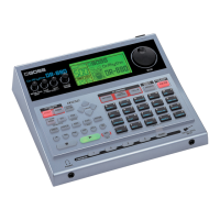
Do you have a question about the Boss Dr. Rhytm DR-550 MK II and is the answer not in the manual?

Boss Dr. Rhytm DR-550 MK II Specifications

General IconGeneral
Sound SourcesPCM
Polyphony8 voices
Tempo40-250 BPM
MIDIIn, Out
TypeDrum Machine
Power9V DC
Power Supply9V DC
InputsFootswitch
OutputsStereo (L/Mono, R)

Summary

Specifications

Tone, Polyphony, and Memory

Details on internal tones, max polyphony, and memory capacity.

Tempo, Sync, and Audio

Specifications for tempo, external sync, and audio output levels.

Power and Battery Information

Details on power source, current draw, and battery life.

Physical and Accessory Details

Dimensions, weight, accessories, and options.

Exploded View and Parts List

Exploded View Diagram

Visual representation of the unit's components and their assembly.

Parts Identification

Lists parts with their numbers referenced in the exploded diagram.

Disassembly and Precautions

Shield Cover Handling

Steps for removing and installing the shield cover.

Main Board and LCD Precautions

Important notes for handling the main board and installing the LCD.

Parts List and Ordering

Safety Precautions for Parts

Safety warnings related to component replacement.

Parts Ordering Guidelines

Instructions for specifying and ordering replacement parts.

Component Categories

Lists parts by category such as Casing, Jacks, and ICs.

Block Diagram and Circuit Description

Main Board Block Diagrams

Visual block diagrams for Main Board (1/2) and (2/2).

LSI Circuit Functionality

Explanation of the main LSI's role and key functions in the circuit.

Main Board Assembly Views

Main Board Assy (1/2) - Component Side

Detailed view of the Main Board Assy (1/2) from the component side.

Main Board Assy (2/2) - Component Side

Detailed view of the Main Board Assy (2/2) from the component side.

Circuit Diagrams (Main Board)

Main Board 1/2 Circuit Schematic

Detailed circuit schematic for Main Board (1/2).

Main Board 2/2 Circuit Schematic

Detailed circuit schematic for Main Board (2/2).

System Setup Procedures

Identifying Version Number

Procedure to check the firmware version number.

Setting Factory Presets

Steps to initialize and set factory presets.

Data Save and Load Operations

Instructions for saving and loading user data via tape.

Test Mode Operations

Entering and Exiting Test Mode

Steps to access and leave the test mode.

Key and LCD Functionality Tests

Tests for key input and LCD display.

Memory and ROM Integrity Tests

Procedures to verify RAM and ROM data.

Tape Save and Load Verification

Steps to test tape data saving and loading.

Troubleshooting Guide

No Sound and Signal Issues

Diagnosing problems related to sound output and signal integrity.

Button and Playback Failures

Steps for issues with button detection, playback, and mode changes.

Tape Functionality Errors

Troubleshooting for data save, verify, and load errors.

Integrated Circuit (IC) Data

CPU, Gate Array, and Logic ICs

Pin assignments for Mask CPU, Gate Array, and NAND Gate.

Converters, Regulators, and Transistors

Pinouts for D/A Converter, Voltage Regulators, and Transistors.

Appendix: Error Messages

MIDI Processing and Connection Errors

Explains errors related to MIDI message processing and cable connections.

Data Verification and Load Errors

Explains errors encountered during data verification and loading.

Errata and Supplement

Parts List Correction

Correction for the Rubber Switch part number in the Parts List.

Related product manuals