EasyManua.ls Logo

Boston Scientific EKOS Control System 4.0 User Manual

Boston Scientific EKOS Control System 4.0
61 pages
To Next Page IconTo Next Page
Page #1 background imageLoading...
Page #1 background image
Boston Scientic (Master Brand, Spiral Bound Manual Template, 8.5in x 11in Global, 92310058G), IFU, MB, CU4, en, 51011236-001A
Black (K) ∆E ≤5.0
EKOS
Control System 4.0
Console
User’s Manual ������������������������������������������ 2
CV03

Table of Contents

Question and Answer IconNeed help?

Do you have a question about the Boston Scientific EKOS Control System 4.0 and is the answer not in the manual?

Boston Scientific EKOS Control System 4.0 Specifications

General IconGeneral
BrandBoston Scientific
ModelEKOS Control System 4.0
CategoryMedical Equipment
LanguageEnglish

Summary

DEVICE DESCRIPTION

EKOS Device

Describes the EKOS Endovascular Device, including the Infusion Catheter and Ultrasonic Core.

EKOS Control System 4.0

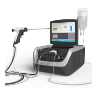
Details the Control Unit and its components, including ports and power.

OPERATING PRINCIPLE

SYSTEM OVERVIEW

INTENDED USE

INDICATIONS FOR USE

CONTRAINDICATIONS

WARNINGS

PRECAUTIONS

ADVERSE EVENTS

CONFORMANCE TO STANDARDS

Classification

Details compliance with ISO standards, device classification, and ratings.

HOW SUPPLIED

Device Details

Instructions for checking package integrity and labeling.

Cleaning the Control Unit

Provides warnings and guidelines for cleaning the Control Unit and cables.

OPERATIONAL INSTRUCTIONS

Environmental Conditions

Specifies operating and storage conditions for humidity, temperature, and pressure.

Required Items

Lists necessary items for EKOS Control Unit 4.0 operation.

EXPECTED SERVICE LIFE

ULTRASOUND OPERATION

SYSTEM CONFIGURATIONS

PREPARING FOR ULTRASOUND USE

POWER MANAGEMENT

AC Power / Battery Status Indicator

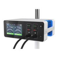
Shows connection and battery charging status when the Control Unit is ON.

BATTERY GAUGE

LOW BATTERY NOTIFICATION

CRITICALLY LOW BATTERY

BATTERY ERROR

BATTERY CHARGING INDICATOR – CONTROL UNIT TURNED OFF

STARTING ULTRASOUND

Activate Screen

Displays channels available for activation after Control Unit start-up.

CONNECT INTERFACE CABLE

CONNECT DEVICE CABLES

READY SCREEN

MONITORING ULTRASOUND

One Channel with Ultrasound Running Screen

Shows runtime and running status for a single active channel.

TWO CHANNELS WITH ULTRASOUND RUNNING SCREEN

ULTRASOUND PAUSED/READY SCREEN

TRANSPORTING THE PATIENT AND CONTROL UNIT

DISPOSAL

COMPLETING ULTRASOUND

Ready Screen Showing Disable Button

Shows the Ready screen with an option to disable a channel.

INFORMATION TO BRIEF THE PATIENT

SYSTEM INFORMATION

TROUBLESHOOTING

Power Graph

Explains how to read and interpret the power graph for therapy delivery.

SCREEN LAYOUT - POWER GRAPH

EXAMPLE POWER GRAPHS

SNAPSHOT

SYSTEM ERRORS

TECHNICAL SUPPORT

Unrecoverable Control Unit Error

Troubleshooting steps for system failure errors (E007).

Critically Low Battery Error

Troubleshooting steps for low battery errors (E003).

BATTERY/CHARGE ERROR (AC NOT CONNECTED)

CONTROL UNIT IS TOO HOT

CONTROL UNIT IS TOO COLD

DEVICE CABLES ARE CROSSED

CHANNEL A CONNECTION ERROR

CHANNEL B CONNECTION ERROR

TECHNICAL SUPPORT CONTACTS

CATHETER CONNECTOR ISSUES

CHANNEL ERROR

ULTRASOUND CONNECTOR ISSUES

INCOMPATIBLE CATHETER/CORE

ULTRASONIC CORE INSERTION

CIC CONNECTION TO CONTROL UNIT

REPLACE CONNECTOR INTERFACE CABLE

DEVICE CONNECTOR ISSUES

CHANNEL MESSAGES

INFUSION STAND

Selecting the Appropriate Infusion Stand

Guidelines for choosing an infusion stand for mounting the Control Unit.

ATTACHING CONTROL UNIT TO INFUSION STAND

SYMBOLS AND INDICATORS

SPECIFICATIONS

WARRANTY

SYMBOL DEFINITIONS

Related product manuals