When tting the cooler into the pipe work, care must be taken to ensure that
no debris has been introduced into the primary or secondary circuits.
Unsupported lengths of pipework should be avoided so as not to subject the
cooler to excessive loads.
Water side pipework diameter should not reduce to less than the connection
size within a distance of 1m from the cooler.
Measures should be taken to isolate the cooler from excessive vibration. Water
pipe connections are parallel thread. Taper pipe ttings are not recommended
as they can split the end cover if over tightened.
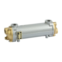
The charge air inlet and outlet are designed to have hose connections using
hose clamps apart from the PK and RK cooler sizes which have ange
connection faces.
Please ensure that the connection ow area is maintained into the cooler and
avoid tight bends to prevent excessive pressure loss.
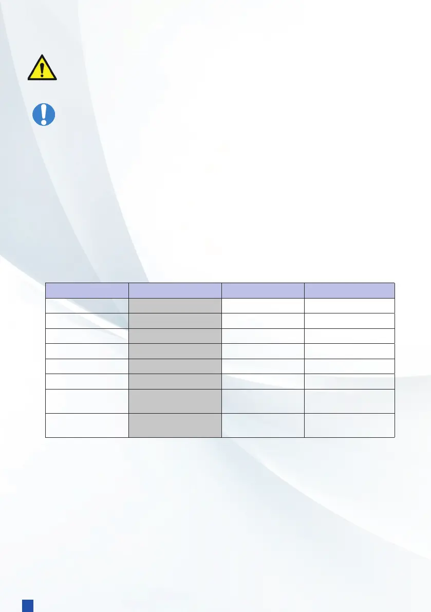
Type Connection Type
Size Water Connections
EC120 Hose
52 mm ¾” BSP
FC100 Hose
52 mm 1” BSP
FG100 Hose
76 mm 1¼” BSP
GL140 Hose
76 mm 1½” BSP
GK190 Hose
89 mm 2” BSP
JK190 Hose
102 mm 2½” BSP
PK250 PN6 Flange
4 x M16 x 32mm on a
170mm PCD
3” BSP
RK250 Flange
4 x M16 x 32mm on a
212mm PCD
8 x 18mm on a 180mm
PCD (PN6-DN100)
Pipework materials must be compatible with the cooler materials.
Stainless steel sea water pipes and ttings should not be used adjacent
to the cooler.
2.3 Connecting the cooler
Take Care
2
6