Bischoff & Bischoff GmbH | 01.06.2019
EN
3332
Alevo Alu / Country | Rollator Rollator | Alevo Alu / Country
4. Assembly/adjustments
4.1. Unfolding
• Position the rollator in the travel direction.
• Release the locking brakes (see sec. 4.6.).
• Press the frame tubes of the seat downward to unfold the rollator
(Fig. 4). Make sure the tubes are aligned properly and snap into
place.
4.2. Folding
• Activate the locking brakes.
• Hold the rollator firmly with one hand on the handle. With your
other hand pull the grip on the seat upward (Fig. 5).
• When doing so you must overcome the resistance of the locking
device.
4.3. Attaching the bag
• The rollator is unfolded. Activate the locking brakes.
• Position yourself against the travel direction in front of the rollator.
• Pull the straps of the bag over the two plastic handles (Fig. 6).
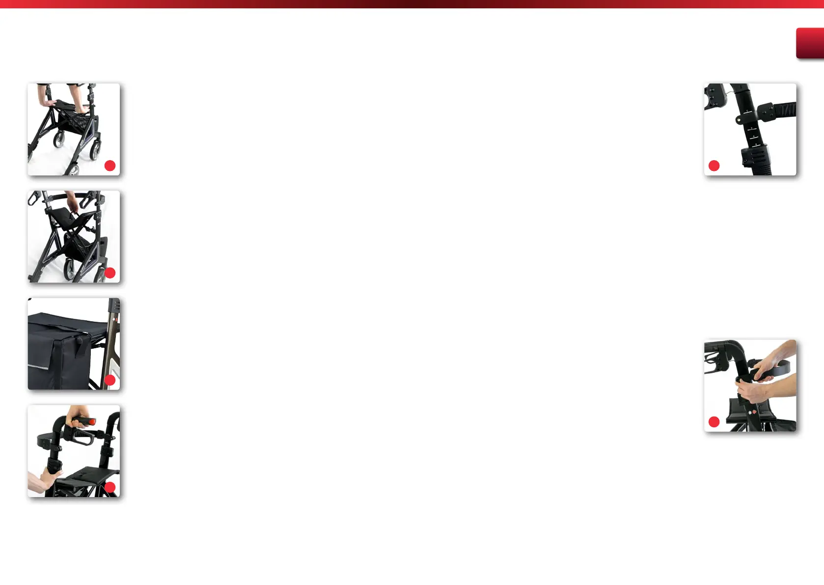
4.4. Adjusting the push handles
• The rollator is unfolded. Activate the locking brakes.
• Hold the push handle firmly with one hand. With the other hand,
activate the locking device (Fig. 7).
• Move the push handle to the desired height and let go of the
locking device.
• Now move the push handle up and down slightly to ensure that it
snaps audibly into place.
• Repeat this procedure on the other side.
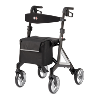
• On the inside of the push handles you‘ll find a scale (Fig. 8), which
you can use to check the height of the handle. Make sure that both
the number and the marking line is visible.
• Check to make sure that both the push handles are at the same
height.
Setting the push handle height according to body
height.
Level 0 – 1.59 cm or taller
Level 1 – 1.65 cm or taller
Level 2 – 1.70 cm or taller
Level 3 – 1.75 cm or taller
Level 4 – 1.80 cm or taller
Level 5 – 1.85 cm or taller
Level 6 – 1.90 cm or taller
Use these figures as guidelines; they may vary in practice.
4.5. Adjusting the back strap
• To adjust the height of the back strap, the hand screws on the
frame (Fig. 9) must be loosened.
• Move the fastener for the back strap to the desired height and re-
tighten the screws.
• The fasteners for the back strap should be at the same height on
both sides.
4
5
6
8
9
7
 Loading...