1
CODIFICATORE/
DECODIFICATORE DI PIANO
CD/204
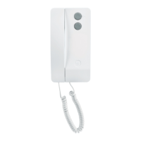
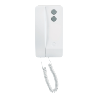
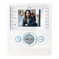
L’apparecchio permette di instal-
lare il citofono C/200 ed i monitor
serie VM/200, VM/203, VMF/200 e
VMF/203 in impianti con chiamata
codificata.
Il CD/204 permette il collegamen-
to di 4 derivati interni ed é quindi
una soluzione ottimale per la codi-
fica/decodifica al piano.
Ad una uscita del CD/204 può
venire collegato un solo derivato
più un ripetitore di chiamata
RC/200.
L’apparecchio, per le sue ridotte
dimensioni, può essere inserito in
una normale scatola di derivazio-
ne (90 x 90 x 40 mm) oppure
installato su guida DIN (EN 50022)
(fig. 3).
Funzione dei morsetti (fig. 1)
Morsettiera C-IN
5 −
10 ÷ 18 Vcc alimentazione
6 +
7 chiamata codificata dal posto
esterno
12 chiamata codificata al centra-
lino di portineria
N2 abilitazione seconda nota di
chiamata
Morsettiera C-OUT
P chiamata al centralino di
portineria dal derivato 1
7A chiamata al derivato 1
P chiamata al centralino di
portineria dal derivato 2
7A chiamata al derivato 2
P chiamata al centralino di
portineria dal derivato 3
7A chiamata al derivato 3
P chiamata al centralino di
portineria dal derivato 4
7A chiamata al derivato 4
Programmazione
- Alimentare l’apparecchio e
togliere il ponticello di program-
mazione SW (fig. 1).
- Inviare il codice relativo all’uten-
te collegato all’uscita 1 tramite il
posto esterno a chiamata codifi-
cata oppure il centralino di porti-
neria VPD/100.
Se a questo punto viene inserito il
ponticello di programmazione, i
codici successivi a quello tra-
smesso, vengono assegnati in
sequenza agli altri 3 utenti. Se
invece si desidera attribuire ad
ogni utente un codice non pro-
gressivo, inviare il codice relativo
all’utente collegato all’uscita 2
quindi quello relativo all’utente col-
legato all’uscita 3 ed infine quello
relativo all’utente collegato all’u-
scita 4.
- Inserire il ponticello SW.
NOTA. Se la programmazione
viene effettuata mediante il centra-
lino di portineria, la conferma del-
l’avvenuta programmazione viene
data dalla comparsa sul display
CHIAMATA PORTIERE del codice
inviato al derivato interno.
L’apparecchio genera due tipi di
nota di chiamata:
a: nota continua bitonale della
durata minima di un secondo;
b: squilli della durata di 0,6 secon-
di ripetuti ogni 2 secondi, per la
durata della chiamata con un mini-
mo di 2 squilli.
L’apparecchio viene fornito pro-
grammato con la nota di tipo a per
la chiamata dal posto esterno e
con la nota di tipo b per la chia-
mata dal centralino di portineria
(per avere la chiamata di tipo b è
necessario effettuare il collega-
mento al morsetto N2). È possibile
invertire il tipo di nota di chiamata
inviando all’apparecchio il codice
80160 (codifica a blocchi) oppure
13120 (codifica in modo progres-
sivo).
Per ritornare alle condizioni inizia-
li, inviare all’apparecchio il codice
80161 (codifica a blocchi) oppure
13121 (codifica in modo progres-
sivo).
La modifica della nota di chiamata
deve essere effettuata in modo
programmazione (ponticello SW
disinserito).
Caratteristiche tecniche
• Alimentazione: 10 ÷ 18Vcc.
• Corrente assorbita: 8mA (110mA
durante la chiamata).
• Numero massimo di CD/204
collegabili in un blocco: 200.
• Temperatura di funzionamento:
da 0 °C a +35 °C.
• Dimensioni: 60 x 44 x 16 mm.
3
BPT S.p.A.
30020 Cinto Caomaggiore
Venezia/Italy
CD/204
I
ISTRUZIONI PER
L’INSTALLAZIONE
1
2
3
4
GB
INSTALLATION
INSTRUCTIONS
FLOOR
CODER/DECODER CD/204
The unit enables the C/200 hand-
set, the VM/200 - VM/203 series
monitors and VMF/200 - VMF/203
monitors to be installed in coded
call installations.
The CD/204 unit enables 4 recei-
vers to be connected and is the-
refore an excellent solution for
encoding/decoding on the floor.
Only one receiver plus an RC/200
call repeater can be connected to
a CD/204 output.
Owing to its small size, the unit
can be inserted in a regular con-
nector box (90 x 90 x 40 mm), or
can be installed on a DIN guide
(EN 50022) (fig. 3).
Function of each terminal (fig. 1)
Terminal block C-IN
5 − 10 ÷ 18V DC
6 + supply voltage
7 coded call from entry panel
12 coded call to porter’s switch-
board
N2 enabling of second call note
Terminal block C-IN
P call to porter’s switchboard
from receiver 1
7A call to receiver 1
P call to porter’s switchboard
from receiver 2
7A call to receiver 2
P call to porter’s switchboard
from receiver 3
7A call to receiver 3
P call to porter’s switchboard
from receiver 4
7A call to receiver 4
Programming
- Power up the unit and remove
the SW software programming
jumper (fig. 1).
- Send the code relating to the
user connected to output 1 via the
coded call entry panel, or the
VPD/100 porter’s switchboard.
If the programming jumper is
inserted at this point, the codes
following the one transmitted are
assigned to the other 3 users in
sequence.
If, on the other hand, the installer
wishes to assign each user a non-
progressive code, send the code
relating to the user connected to
output 2, followed by the code
relating to the user connected to
output 3, and lastly the code rela-
ting to the user connected to out-
put 4.
- Insert the SW jumper.
N.B. If the programming is carried
out via the porter’s switchboard,
the acknowledgement of the com-
pleted programming is given by the
code sent to the extension appea-
ring on the display (PORTER
CALL).
The unit generates two types of
call note:
a: continuous bi-tonal note lasting
at least one second;
b: rings lasting 0.6 seconds repea-
ted every 2 seconds, for the dura-
tion of the call, with a minimum of
2 rings.
The unit is factory set with the note
type a for calls from the entry
panel, and with note type b for
calls from the porter’s switchboard
(the connection must be made to
terminal N2 before note type b can
be obtained).
The type of note can be inverted
by sending the code 80160 (block
code) or 13120 (progressive-
mode code) to the unit.
In order to reset the initial condi-
tions, send the code 80161 (block
code) or 13121 (progressive-
mode code) to the unit.
The modification of the call note
must be carried out when in pro-
gramming mode (with the SW
jumper disconnected).
Technical features
• Supply voltage: 10 ÷ 18 VDC.
• Current demand: 8mA (110 mA
during call).
• Maximum number of CD/204
units which can be connected
in a block: 200.
• Working temperature range:
from 0°C to +35°C.
• Dimensions: 60 x 44 x 16 mm.
1
2
3
4
12.97/2403-5500