22
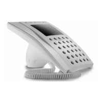
Fig. 22 - Connection diagram of
auxiliary door-lock release button
(AE).
Fig. 22 - Esquema de conexión del
pulsador auxiliar abrepuerta (AE).
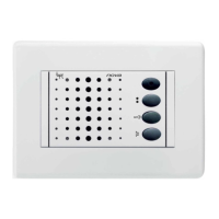
Fig. 23 - Colour coding of wires
relating to CN3-CN4-CN5.
Fig. 23 - Color de los conductores
correspondientes a los cableados
CN3-CN4-CN5.
CN3
C: orange, naranja
G: yellow, amarillo
R: red, rojo
CN4
M: brown, marrón
N: black, negro
CN5
G: yellow, amarillo
H: grey, gris
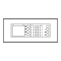
20
Fig. 20 - Sample connection of
Aux 1 or Aux 2 auxiliary output with
relay unit VLS/101.
Power supply by means of VAS/100.
Fig. 20 - Ejemplo de conexión sali-
da auxiliar Aux 1 ó Aux 2 con la uni-
dad relé VLS/101.
Alimentación mediante VAS/100.
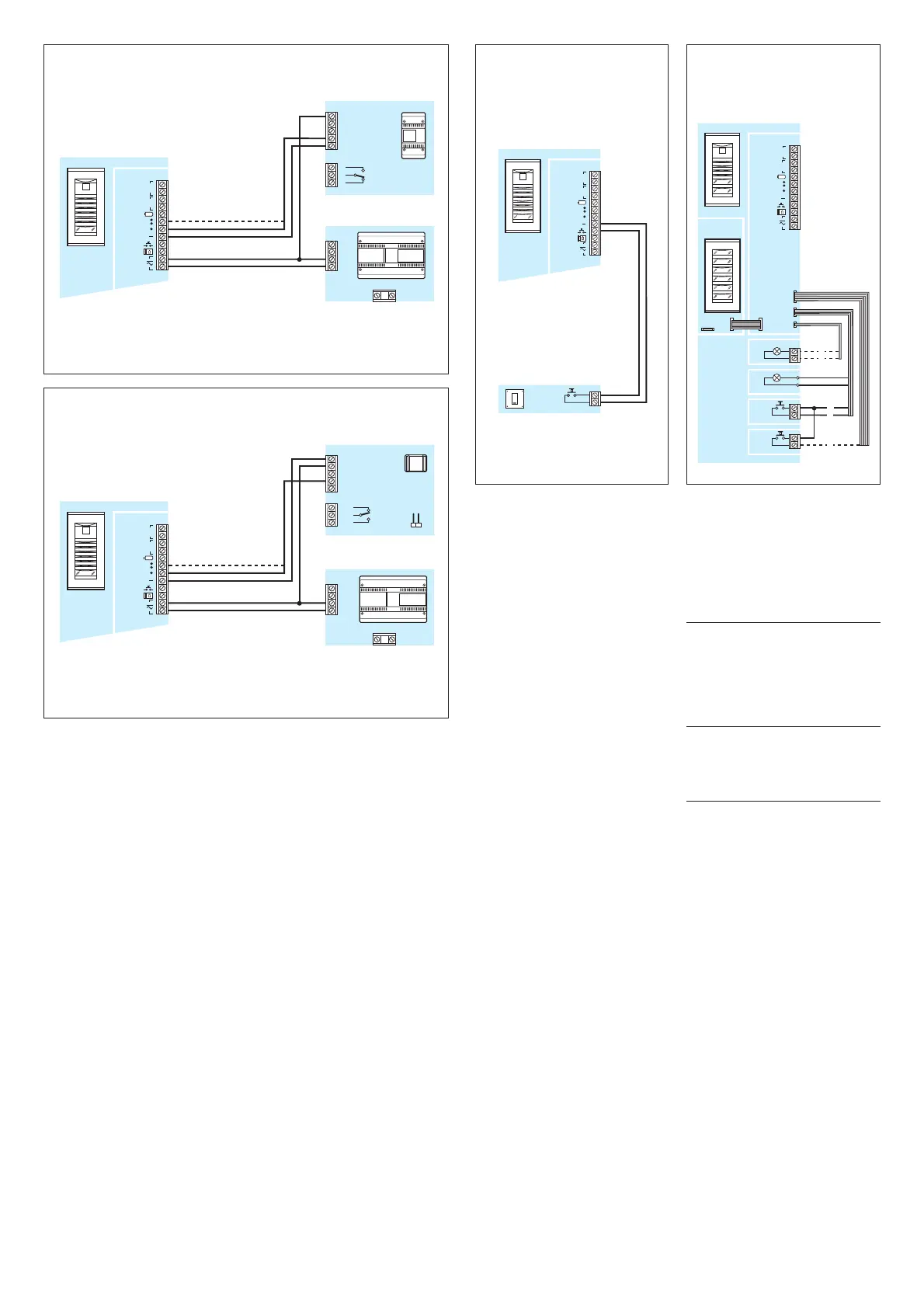
Fig. 21 - Ejemplo de conexión sali-
da auxiliar Aux 1 ó Aux 2 con la uni-
dad relé AC/200.
Alimentación mediante VAS/100.
Fig. 21 - Ejemplo de conexión sali-
da auxiliar Aux 1 ó Aux 2 con la uni-
dad relé AC/200.
Alimentación mediante VAS/100.