3
LED 2 Yellow LED can be used to indicate an
external function
LED 3 Red LED can be used to indicate an
external function.
LED 3 cannot be utilised with the monitor
in the table-top version (VM/100+
VKT/100).
Switches Aux 1 and Aux 2 are normally open,
when actuated the contacts close on
−
0 V DC.
Max. current demand 100 mA at 24 V.
To activate LED 1, 2 and 3 line 13, 14 and 15
respectively should be connected via an external
switch device which is common to terminal 5 of
the system, 0 V DC.
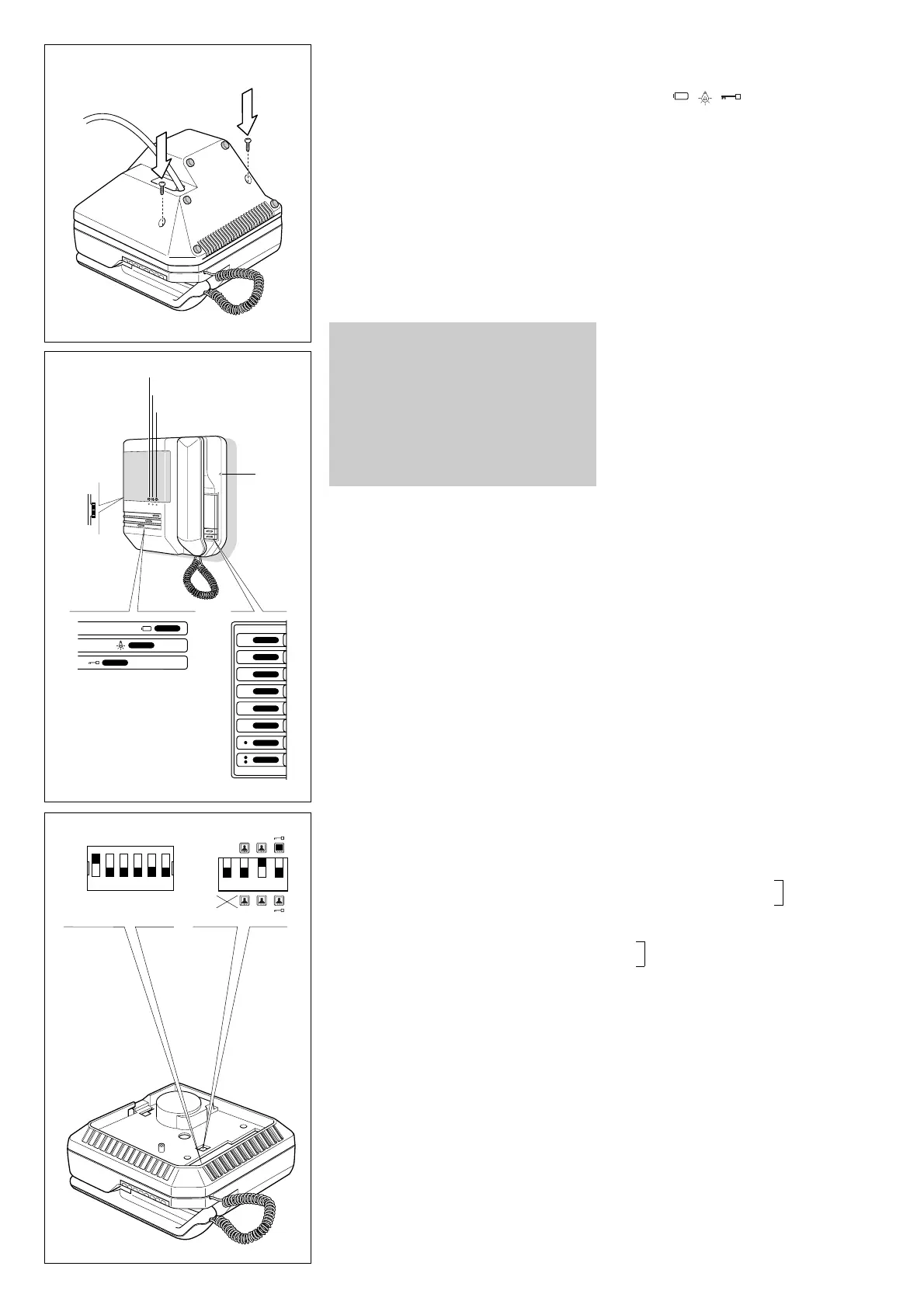
The monitor is protected by the slow blow fuse
F1 - T 630 mA - located on support’s printed
card, figures 3-5. (Fuse: F = fast, T = slow).
WARNINGS FOR THE USER
- Please do not open or tamper the device (high
voltage!).
- Please avoid knocking or bumping the appara-
tus as it could result in the breakage of the pictu-
re tube and the consequent projection of glass
fragments.
- In the case of breakdown or modification of the
apparatus of the system (such as power sup-
plier…) please contact a specialized maintenan-
ce service.
Four special monitor operation modes can be
chosen by means of dip-switches C accessible
from the rear of the monitor. Figure 2 shows posi-
tion of dip-switches as supplied.
• Stand-by mode
The dip-switch 1 is normally kept in the OFF
position - the stand-by mode is not operating -
the picture appears on the screen in 4 seconds
approx.
In the ON position it activates the stand-by, the
picture appears on the screen almost instanta-
neously.
• Monitor in constant mode
For use only in single house installations as
close circuit television system with camera
always powered and separated from entry
panel. VM/100 is supplied from the factory with
dip-switch 2 in the OFF position. The constant
mode is achieved with dip-switch 2 set to ON
position. The monitor can only be switched off
by thumb-wheel switch D, figure 1.
• Activation of more monitors by the same
call
Dip-switch 3 is normally kept in the ON position,
this way the call line loop is closed. If more moni-
tors must be activated by the same call, leave
only one with the dip-switch 3 in the ON position,
all other monitors must have the dip-switch 3 in
the OFF position. Failure to have the dip-swit-
ches in the correct positions will result in the
monitors not being activated.
• Monitor/system turned off on door release
a) Systems with VA/100 main control unit
Dip-switch 4 is normally kept in the OFF position.
In this position the monitor is turned off automa-
tically by the system timer. Whit dip-switch 4 in
the ON position the monitor is turned off by pres-
sing the door lock release button.
b)Systems with VA/100.
01 main control unit
Dip-switch 4 must be in the OFF position.
Use dip-switch 2 of the VA/100.
01 main control
unit to turn off the monitor.
Call tone
It is possible to regulate the call tone level from
the entry panel by adjusting the trimmer, acces-
sible from the A hole placed on the right side of
the monitor, figure 1.
System using main control unit VA/100.
01 has a
timed call feature.
The call stops either when the handset is lifted or
when any button is pressed.
Personal door-bell
When the personal door-bell is required to be
part of the video entry system, insert the ER/12
buzzer on the guides of VKP/100 wall mounting
kit, figure 11, and connect the wires as shown in
diagram of figure 12.
VM/106.
01 HANDSET MONITOR
WITH INTERCOM FACILITY
VM/106 in addition to features of VM/100 is
equipped with 6 intercom call buttons and the
red light (LED 3) is used to indicate when the
intercom audio line is engaged, figure 9.
A maximum of 6 video intercom units can com-
municate to each other. The main features are:
• Easy to install. Intercom units are connected in
parallel to each other with 4 additional wires of
0.28 mm
2
(Ø 0.6 mm) cross-section.
• Intercom call tone different from that of entry
panel.
• Audio privacy. Intercom and entry panel audio
are separated. It is thus possible to continue an
intercom conversation while answering from
another monitor to an entry panel call.
• A call code - from 1 through 6 - can be given
to each monitor matching the intercom call but-
ton, figure 9, by setting the corresponding dip-
switch B to the ON position.
Dip-switches B are accessible from the rear of
the monitor, figure 10.
• All connected monitors can call each other.
• The monitor intercom audio line be occupied
until the caller has replaced the handset. The
red light LED indicates when the intercom audio
line is engaged.
• Installation with a mix of monitors with and
without intercom facility is possible.
Four special monitor operation modes can be
chosen by means of dip-switches C, figure 10,
accessible from the rear of the monitor as model
VM/100.
Function of each terminal
from 1 to 15: terminals for connection to
VKP/100 with VM/100 standard monitor.
from 1 to 14: terminals for connection to
VKT/100 with VM/100 standard monitor.
from 1 to 18: terminals for connection to
VKP/100 or VKT/124 with VM/106 intercom
monitor.
1 video signal
(
1
)
2 video signal shield
3 video signal
4 video signal shield
5 – 14 ÷ 17.5 V
6+supply voltage to monitor
7 call
8 audio to monitor
9 audio to entry panel
10 +11.5V DC voltage output (
2
)
or
input to turn on monitor when connected to
positive voltage system (+15÷17.5 VDC)
11 Aux 1
12 Aux 2
13 LED 1 (green)
14 LED 2 (yellow)
15 LED 3 (red)
16 audio intercom.
17 audio intercom.
18 intercom call code
(
1
) 75 Ω closing resistance if video line stops here.
(
2
) This voltage output is available for the time the
monitor is operating.
Max. current demand should not exceed 50mA.
 Loading...