Terminal block C
1 ground
2 audio from receivers
3 audio to receivers
5 +12 V DC for auxiliary services
6 call common to handsets
NOTE.The power supplier is equip-
ped with two terminal blocks D-E
which are connected to each other
to facilitate the connection of call
wires in systems whith 1 and 2
calls.
Terminal block D
1 call n.1 from entry panel
2 call n.2 from entry panel
Terminal block E
1 call n.1 to handset
2 call n.2 to handset
Technical features
• Mains: 230 V AC 50/60 Hz.
The transformer primary is elec-
tronically protected against over-
loading and short circuiting i.e.
no fuses are used.
• Rated power: 10 VA.
• Output voltages, electronically
protected:
12 V DC 150 mA, supply voltage
to entry panel and auxiliary servi-
ces as required.
15 V AC 400 mA, supply voltage
call buttons lamps.
12V AC 1 A, supply voltage to
door release solenoid.
• Electronic dual-tone note for call
made from entry panel.
• Single tone for intercom call.
Since the call signal is applied to
the loudspeakers of handsets,
we recommended to avoid con-
nection of no more than 3 hand-
sets in parallel to the same call.
This to avoid a decrease in call
volume.
• Working temperature range: from
0 °C to + 35 °C.
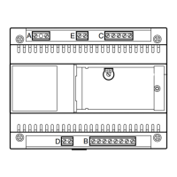
• Dimensions: 8 DIN units module,
low profile, figure 2.
The unit can be installed without
terminal covers into boxes provi-
ded with DIN rail (EN 50022).
Dimensions are shown in figure 2A.
Or it can be wall-mounted using
the DIN rail provided, applying as
necessary the terminal covers and
plugs provided.
Dimensions are shown in figure 2B.
NOTE. The transformer primary is
electronically protected against
overloading and short circuiting i.e.
no fuses are used.
a) Disconnect the mains from the
unit.
b) Remove the cause of malfunc-
tion.
c) Let the equipment to cool for at
least 1 minute.
d) Reconnect the mains to the unit.
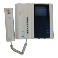
C/200 HANDSET
The handset call tone is electronic.
When the personal door-bell is
required to be part of the audio
entry system, insert the ER/12 buz-
zer in the apposite guide in the
handset.
It can accommodate the module
P3.
3
GB
INSTALLATION
INSTRUCTIONS
Attention.
Before installing the unit, care-
fully read the “WARNINGS FOR
INSTALLATION” contained in the
package.
POWER SUPPLIER E/310.01
This units is used to create simple
intercommunication systems with a
maximun of 3 internal units to ena-
ble both communication between
internal units and the entry panel.
Audio intercom installations, limi-
ted to 2 handsets, can be made
using standard handset. The auxi-
liary button is used for the inter-
com call.
During a conversation between
internal units the power supplier
guarantees complete audio pri-
vacy (and therefore complete con-
versation confidentiality) with
respect to the entry panel.
The power supplier is equipped
with an amplifier that regulates the
audio volume of entry panel loud-
speaker by means of a potentio-
meter accesible after cover has
been removed, figure 1, and with
an transformer to power the button
illumination lamps in the entry
panel.
The call from the entry panel is
dual tone and a note is heard at the
entry panel confirming the call,
whilst the intercom call is single
tone.
The door lock release solenoid is
activated by a relay contact.
Function of each terminal
(figure 1)
Terminal block A
mains
Terminal block B
4 call common to entry panel
5 audio to entry panel
6 audio from entry panel
7 +12 V DC for entry panel and
auxiliary services
8 ground
9 15 V AC for call button lamps
10 12 V AC for door release sole-
noid
11 0 V AC
It is equipped with the following
controls:
Door lock release button
•
Auxiliary services
Function of each terminal
(figure 8)
Terminal block C
5 ground
7 call
8 audio from entry panel
9 audio to entry panel
•
button for
•
auxiliary services
Technical features
• Max. switching capacity of auxi-
liary services button contact:
max. 24 V, 1 A.
• Working temperature range: 0 °C
to +35 °C.
• Dimensions: 88x220x70 mm.
Installation instructions
Untighten the fixing screw and
remove the front cover from the
back housing, figure 3.
Fix the back housing to the wall,
figure 4, or to an embedding box,
figure 5, 6.
Avoid excessive tightening of the
screws especially when walls are
not perfectly flat.
Make the relative connections and
re-fit the cover (figure 7).
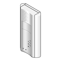
XC/200 HANDSET
Features similar to handset C/200,
it can accommodate the module
XP3.
- Dimensions: 110x224x65 mm.
HANDSET YC/200
Features similar to handset C/200,
it can accommodate the auxiliary
services button ( ) YP1 and loud-
speaker YAL to make the call note
more powerful.
- Dimensions: 98x215x63 mm.
Note. In intercom systems, the
door-lock release button is enabled
while you are talking with the entry
panel.
Door-lock release button
Normally the door-lock release but-
ton is active. If you want it active
only when the receiver is lifted, cut
the jumper BP1 (fig. 10).
HANDSET YC/200A
Features similar to handset
YC/200, it also has a button for
auxiliary services .
- Maximum switching power of
auxiliary services button: max. 24
V, 1 A.
It can accommodate the module
YP3.
AUXILIARY BUTTON YP1
Accessory to be inserted in hand-
set YC/200 so that the Aux 2 auxi-
liary services button ( ) can be
used.
Technical features
• Max. load to relay contact: max.
24 V, 1 A.
• Working temperature range: 0 °C
to +35 °C.
D
INSTALLATIONS-
ANLEITUNG
ACHTUNG.
Um Verletzungen zu vermeiden,
muss dieses Gerät entsprechend
den Installationsanweisungen
an der Wand abgesichert sein.
NETZGERÄT E/310.01
Das gerät wird für einfache
Intercom-Systeme mit maximal 3
Innensprechstellen verwendet und
gewährleistet auch deren Verbin-
dung zur Außenstation.
Intercom-Sprechanlageninstalla-
tion mit bis zu 2 Hörer Standard.
Die Hilftaste wird als Intercom-
Ruftaste verwendet.
Während eines Gespräches zwi-
schen Intercom-Innesprechstel-
len, garantiert dieses Gerät die vol-
P3-XP3-YP3 CALL EXPANSION
WITH 3 BUTTONS
Enables transforming a standard
into an intercom handset.
Function of each terminal
(figure 8÷10)
12 call output from entry panel
7 call input from entry panel
13 intercom call common
14 call to handset no. 1
15 call to handset no. 2
16 call to handset no. 3
Intercom handset instructions
for use
Different tones are used to identify
internal from external calls. The
intercom call tone is single note
whilst that from the entry panel is
dual note.
To initiate an internal conversation
lift the handset and press the desi-
red intercom button.
When the call is attended the audio
line to the entry panel is discon-
nected and the intercom conversa-
tion cannot be overheard at the
entry panel.
If during an intercom conversation
there is a call from the entry panel
a softer note is heard in the hand-
set loudspeaker.
In this instance to attend the call it
is first necessary to replace both
handset on the cradle.
DISPOSAL
Do not litter the environment with
packing material: make sure it is
disposed of according to the regu-
lations in force in the country where
the product is used.
When the equipment reaches the
end of its life cycle, take measures
to ensure it is not discarded in the
environment.
The equipment must be disposed
of in compliance with the regula-
tions in force, recycling its compo-
nent parts wherever possible.
Components that qualify as recy-
clable waste feature the relevant
symbol and the material’s abbre-
viation.
l’ambiente, ma smaltito seguendo
le norme vigenti nel paese di utiliz-
zo del prodotto.
Alla fine del ciclo di vita dell’appa-
recchio evitare che lo stesso
venga disperso nell’ambiente.
Lo smaltimento dell’apparecchia-
tura deve essere effettuato rispet-
tando le norme vigenti e privile-
giando il riciclaggio delle sue parti
costituenti.
Sui componenti, per cui è previsto
lo smaltimento con riciclaggio,
sono riportati il simbolo e la sigla
del materiale.
 Loading...