18
2. Install both halves of the split ring (item 12) around
the output shaft and pry firmly into place against the
shaft. At this point, the output shaft should rotate
smoothly and freely in the housing.
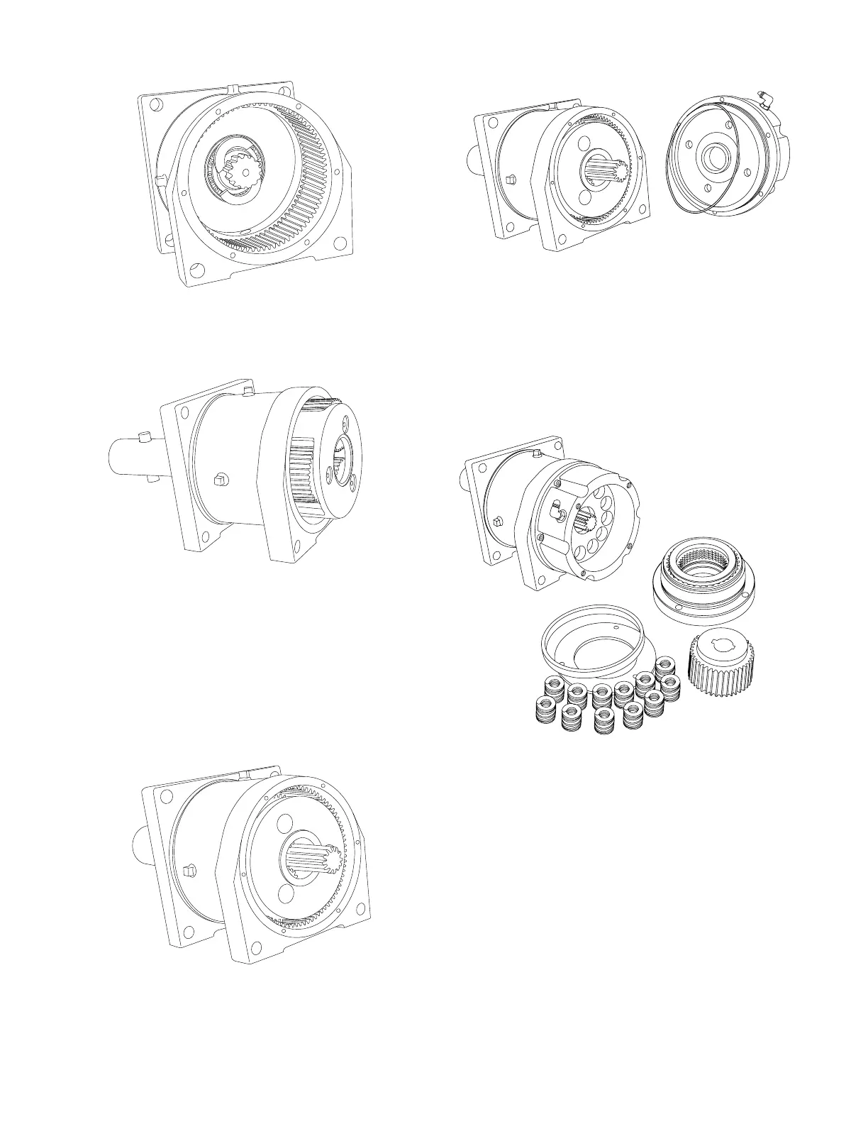
3. Install the planetary gear assembly into the housing.
Rotate the planet gears to engage the ring gear and
rotate the planet carrier, or the output shaft, to engage
the splines on the planet carrier with those on the out-
put shaft. The planet carrier MUST fully engage the out-
put shaft and go over the split ring, holding it in place.
At this point, the planet carrier will be slightly below the
end of the housing. If the planet carrier will not fully drop
into the housing, the split ring may not be fully seated
against the output shaft. DO NOT proceed to the next
step until the planet carrier is properly positioned.
4. Lightly coat the surface of thrust washer (item 21)
with an oil soluble grease and position it on the planet
carrier. Install the sun gear into the center of the planet
gear assembly.
5. Install a new O-ring (item 11) onto the brake cylin-
der (item 2). Install the brake cylinder onto the main hous-
ing, being careful that the thrust washer installed in the
previous step stays in position. Make sure the brake
release port is properly positioned and install the six (6)
socket head capscrews to the proper torque. At this time,
the sun gear should turn freely, without any binding of
the gear train.
6. Install the twelve (12) springs (item 22) into the spring
pockets in the brake cylinder. Set the pressure plate (item
23) onto the springs. Lightly lubricate the brake piston
(item 25) with gear oil and install the piston into the brake
cylinder. Install the brake coupling (item 31) into the brake
discs. The coupling will have to be rotated as it is installed
to align the teeth on the friction discs. The stepped end
of the coupling, with keyways, faces the motor. Carefully
install the motor support/brake assembly into the brake
cylinder taking care to not cut the piston seal or O-rings.
Be careful the spacer plate (item 24) that rests against
the pressure plate remains properly positioned. The brake
coupling may have to be rotated slightly to engage the
sun gear.