2/5 2704_r03
DIRECTIONS FOR INSTALLATION AND MAINTENANCE
• This valve is a safety appliance and should not be
modified. The manufacturer's responsibility and guarantee
are invalidated in case the device is tampered with by the
user.
• The applicable national regulation and European
standards (Ex. EN 60335-1 and EN 60335-2-102) related
to the electrical safety must be respected;
• Assemble the valve to the installation so that the arrow
on the valve body has the same direction as the fuel flow.
• During the assembly of the valve to the installation
piping, avoid twisting on the sheath and always use an
hexagonal wrench to be fitted to the valve body.
• Make sure that no foreign matters have entered the
valve body.
• Make sure that the max. fuel input pressure never
exceeds the value appearing on the label.
• All operations (installation, maintenance, etc.) must be
carried out by a qualified technician.
• Before any connection operation, completely isolate the
system from power supply (multi-pole disconnection).
Place the system safely to avoid accidental switch-on and
make sure there is no voltage. If the system is not
switched off, there is a risk of electric shock.
• During and after any operation (installation,
maintenance, etc.), make sure that the type and code are
the ones provided, check the correct functioning and the
internal and external thickness of the valve.
• In the event of a fall or impact, the valves must not be
started, as safety functions may be compromised even if
no damage is visible to the outside.
• Faulty valves or damaged must be unplugged from power
supply and cannot be used.
• The valve has a designed lifetime* based on the
endurance tests in the standard EN 161. A summary of
the conditions has been published by the European
Control Manufacturers Association (Afecor)
(www.afecor.org). The designed lifetime is based on use
of the valve according to the manufacturer’s technical
notes. After reaching the designed lifetime in terms of the
number of burner startup cycles, or the respective time of
usage, the valve has to be replaced by authorized
personnel.
* The designed lifetime is not the warranty time specified
in the Terms of Delivery
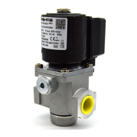
DIRECTIONS FOR EG12*L... VALVES ADJUSTMENT
Flow adjustment for EG12*L...
To adjust the gas flow, you have to remove one of the two
screws used to fasten the lag group (the not enamelled one,
marked with 4 in Fig.1) and rotate clockwise the whole group
to reduce the flow or in the opposite direction to increase it.
Opening time adjustment
After removing the top protection, by rotating it
counterclockwise, you have to act on the adjustment screw,
marked with 1 in Fig.1; by rotating clockwise, the opening
time becomes longer, by rotating in the opposite direction, the
opening time becomes shorter.
Quick release initial flow adjustment
After removing the top protection by rotating it
counterclockwise, if you rotate clockwise the nut marked with
2 in Fig.1, the initial release will be reduced; if you rotate the
same nut counterclockwise, the initial release will be
increased.
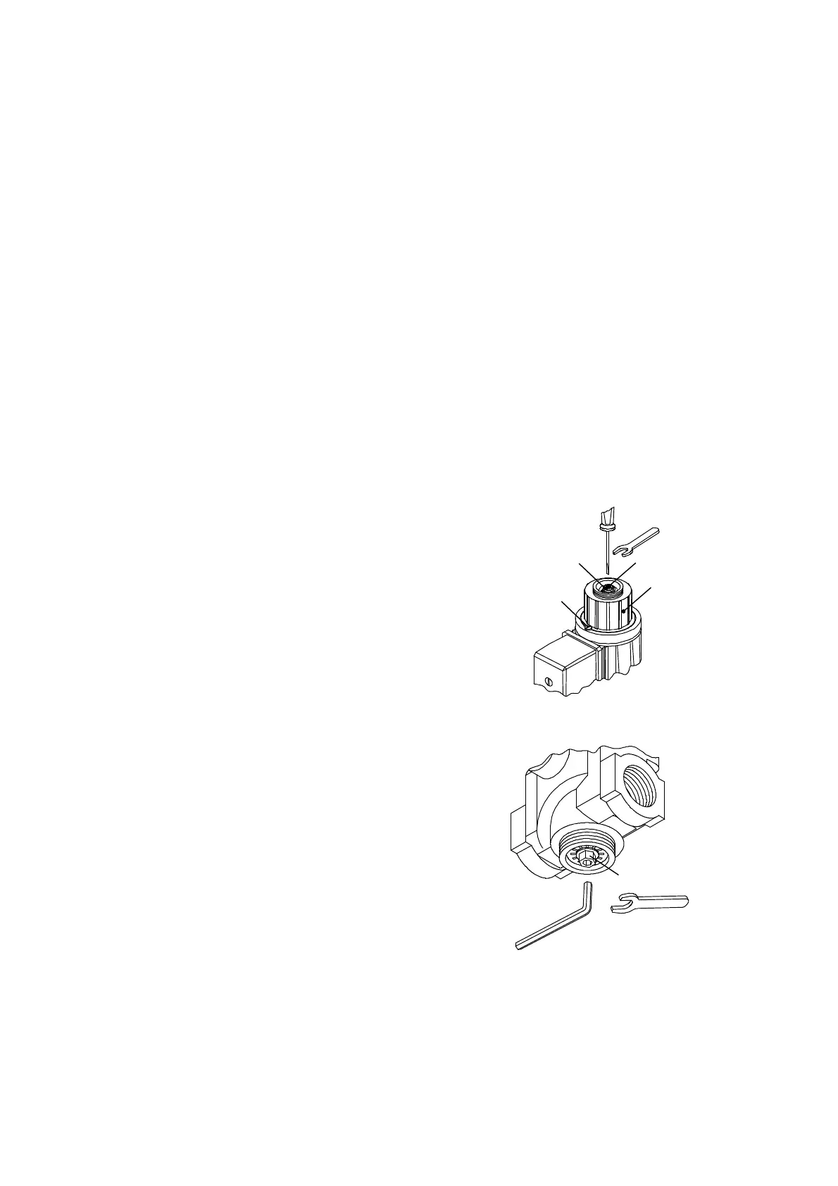
DIRECTIONS FOR EG12*SR... AND EG12*AR... VALVES
ADJUSTMENT
Flow adjustment for EG12*R
After removing the bottom protection by rotating it
counterclockwise, rotate clockwise the nut marked with 1 in
Fig.2 to reduce the flow, rotate in the opposite direction to
increase the same.
2 1
3
4
Fig. 1
1
Fig. 2
 Loading...