7
Drive system
Drive batteries and battery safety box
The
camera
motor
and the
power
zoom
mechanism are
electric
ally powered by six
1.5
volt AA penlight cell batteries. This type
of battery is
obtainable everywhere
for
use
in
transistor
radios.
We
recommend the
use
of
manganese-alkaline cells (for ex-
ample, Mallory MN 1500, Everready E
94,
Ucar
E 94). The batteries are housed in a
safety box in the camera handgrip.
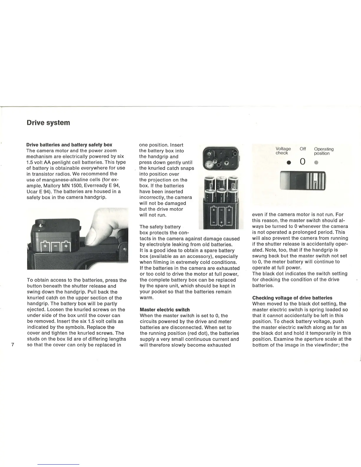
To obtain access to the patteries, press the
button beneath the shutter
release and
swing down the
hal'ldgrip. Pull back the
knurled catch on the
upper
section of the
handgrip. The battery box
will
be partly
ejected. Loosen the
knurled
screws
on the
under
side of the box until the
cover
can
be removed.
Insert the six 1.5 volt cells as
indicated by the
symbols. Repl'ace the
cover and tighten the
knurled screws. The
studs on the box
lid are of
differing
lengths
so
that
the cover can only be replaced in
one position.
Insert
the battery box into
the handgrip and
press down
gently
until
the knurled catch snaps
into position over
the projection on the
box.
If the batteries
have been inserted
incorrectly, the cainera
will not be damaged
but the drive
motor
will not run.
The safety battery
box protects the con-
tacts in the camera against damage caused
by
electrolyte leaking from
old
batteries.
It
is a good idea to obtain a sp'are battery
box
(available as an accessory), especially
when filming in extremely cold
conditions
.
If the batteries in the camera are exhausted
or
too cold to drive the
motor
at full power,
the
complete battery box can be replaced
by the spare unit, which should be kept in
your pocket so
that
the batteries remain
warm.
Master electric switch
When the master switch is set to
0,
the
circuits
powered by the
drive
and meter
batteries are
disconnected
. When set to
the running position (red dot), the batteries
supply a very small
continuous
current
and
will
therefore
slowly
become
exhausted
Vo
lt
age
ch
ec
k
•
O
ff
Ope
ra
tin
g
pos
iti
on
o •
I
J~~fl
even
if
the camera
motor
is
not run.
For
this reason, the master switch should al-
ways be turned to ° whenever the camera
is
not
operated a
prolonged
period. This
will also prevent
the
camera from running
if the shutter
re·lease
is
accidentally
oper-
ated. Note, too,
that
if
the handgrip is
swung back
but
the master switch
not
set
to
0,
the meter battery will continue to
operate at
full
power
.
The
black
dot
indicates
the switch setting
for
checking the
condition
of the drive
batteries.
Checking voltage
of
drive batteries
When moved to the black
dot
setting, the
master
electric
switch is spring loaded so
that it
cannot
accidentally
be left in this
position. To check battery
voltage, push
the master
electric
switch along
as
far as
the
black
dot
and
hold
it
temporarily in this
position. Examine the aperture
scale at the
bottom of the image in the viewfinder; the
 Loading...