EasyManua.ls Logo

Braun VISTA Series User Manual

Braun VISTA Series
80 pages
To Next Page IconTo Next Page
Page #1 background imageLoading...
Page #1 background image
3EEINSIDECOVER
FORWARRANTYAND
REGISTRATIONINFORMATION
#OMMERCIAL7HEELCHAIR,IFT
)NSTALLATION3ERVICE-ANUALFOR
!MERICANS7ITH
$ISABILITIES!CT!$!
COMPLYINGWITH
:
$
51,1*
5HDGPDQXDO
EHIRUHLQVWDOOLQJ
RUVHUYLFLQJOLIW
)DLOXUHWRGRVR
PD\UHVXOWLQ
VHULRXVERGLO\
LQMXU\DQGRU
SURSHUW\GDPDJH
XDO
0DQ
0ROVIDING!CCESSTOTHE7ORLD
)NTERNATIONAL#ORPORATE(DQRS0/"OX7INAMAC).53!
4(%,)&4&!8
¤
¤

/CTOBER
0ATENT0ATENT
0ATENT0ATENTS0ENDING
KA.&,>7
KA.&,>7
Question and Answer IconNeed help?

Do you have a question about the Braun VISTA Series and is the answer not in the manual?

Braun VISTA Series Specifications

General IconGeneral
BrandBraun
ModelVISTA Series
CategoryLifting Systems
LanguageEnglish

Summary

Congratulations

Warranty Registration Process

Details on completing and submitting warranty cards to activate coverage.

Identification Tags

Location and purpose of serial/series number identification tags.

Braun Corporation Product Bulletin

Series 02 Supplement Contents

Table of contents for the Series 02 supplement.

Series 02 VL917IB Electrical Schematic

Series 02 VL917IB Wiring Diagram

Lift Interlock Installation

Negative Logic (Grounded) Interlock Installation

Instructions for installing a remote interlock using a ground signal.

Interlock Specifications

Technical requirements for the interlock system.

Lift Interlock Installation

Positive Logic (+12V) Interlock Installation

Instructions for installing a remote interlock using a +12V signal.

Interlock Specifications

Technical requirements for the interlock system.

Pump Module Parts List

Control Box and Harness Options

List of available control box and harness configurations.

Pump Module Diagram

VL917IB Repair Parts List

Lift Exploded View

Lift Terminology

Lift Terminology Illustration

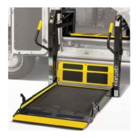
Diagram illustrating lift components and their names.

Lift Components

Detailed description of major lift parts and their functions.

Lift Terminology

Introduction

Overview of the VL917 Series lifts and manual usage.

Direction

Explanation of directional terms used in the manual.

Installation/Service Safety Precautions

Safety Symbols

Explanation of warning and caution symbols used in the manual.

Installation/Service Safety Precautions

Pre-Installation Notes

Minimum Clear Door Opening Requirements

Critical dimensions for vehicle door opening for lift installation.

Obstructions

Identifying and removing obstructions in the installation area.

Pre-Installation Notes

Lift Ground

Requirements for proper electrical grounding of the lift system.

Lift Installation Checklist

A final checklist to ensure proper lift installation.

Lift Installation Instructions

Installation Parts

List of parts included in the installation package.

Tools Required

List of tools necessary for lift installation.

Lift Installation Instructions

Base Plate Mounting

Procedures for securing the lift's base plate to the vehicle floor.

Underfloor Reinforcement Brackets

Installation of reinforcement brackets for base plate support.

Lift Installation Instructions

Lift Positioning

Guidelines for correctly positioning the lift within the vehicle.

Lift Installation Instructions

Clearance

Ensuring adequate space for lift operation and door closure.

Alignment

Steps to align lift components for proper function.

Lift Installation Instructions

Rear Door and Extensive Floor-to-Ground Installations

Specific considerations for rear door and floor-to-ground installations.

Base Plate Wedges

Using wedges for shimming and tilting the lift.

Lift Installation Instructions

Lift Securement

Methods for securely mounting the lift base plate.

Underfloor Reinforcement Brackets

Installation details for reinforcement brackets.

Lift Installation Instructions

Underfloor Reinforcement Brackets (continued)

Continued instructions for installing reinforcement brackets.

Lift Installation Instructions

External Tooth Star Washers

Proper placement of external tooth star washers.

Lift Installation Instructions

Bolt Tightening

Procedures and torque specifications for tightening mounting bolts.

Lift Installation Instructions

Power Cable and Ground Cable Installation

Connecting power and ground cables to the lift.

Lift Installation Instructions

Power Cable and Ground Cable Installation (continued)

Continued steps for power and ground cable connection.

Circuit Sentry Installation and Power Connection

Installing the Circuit Sentry and connecting power.

Lift Installation Instructions

Circuit Sentry Installation and Power Connection (continued)

Continued steps for Circuit Sentry and power connection.

Lift Installation Instructions

Control Box and Harness Installation

Connecting the control box and harness to the pump module.

Lift Installation Instructions

Control Box Mounting

Mounting the control box to the vehicle door.

Harness Routing and Securement

Routing and securing the control box harness.

Lift Installation Instructions

Design Lifting Capacity

Maximum weight capacity of the lift.

Test Lift Operation

Procedures for testing lift functions after installation.

Positioning and Clearance Checklist

Final check for correct positioning and clearances.

Lift Installation Instructions

Alignment

Checking and adjusting the alignment of lift components.

Platform Angle Adjustment

Adjusting the angle of the lift platform.

Lift Installation Instructions

Decal Application

Proper application of safety and operating instruction decals.

Passenger's Seat (Vans)

Specific instructions for reinstalling passenger seats in vans.

Owner's Manual

Ensuring the owner's manual is stored correctly.

Quiet-Ride Adjustment Instructions

Vertical Upright Deflection

Adjusting vertical uprights to prevent rattles and ensure proper alignment.

Quiet-Ride Guided Stop Blocks

Adjusting stop blocks to reduce platform vibration.

Platform Angle Adjustment Instructions

Platform Angle Adjustment Instructions

Floor Level Guideline Adjustments

Unfold/Down and Up/Fold Microswitches

Adjusting limit switches for platform and bridge plate positioning.

Floor Level Guideline Adjustments

Stop Blocks

Ensuring stop blocks make full contact with vertical arms.

Bridge Plate Positioning

Correct positioning of the bridge plate for a level transition.

Lubrication Diagram

Fold Arm Adjustments

Maintenance and Lubrication Schedule

4 Weeks or 400 Cycles

Maintenance tasks and inspections for the 4-week/400-cycle interval.

Maintenance and Lubrication Schedule

3 Months or 1200 Cycles

Maintenance tasks and inspections for the 3-month/1200-cycle interval.

Maintenance and Lubrication Schedule

1 Year or 4800 Cycles

Maintenance tasks and inspections for the 1-year/4800-cycle interval.

Maintenance and Lubrication Schedule

Systems Descriptions

General Operation

Overview of how the VL917 lift operates automatically.

Electrical

Description of the lift's electrical system components and power sources.

Systems Descriptions

Electrical (continued)

Further details on electrical components like circuit breakers and solenoids.

Systems Descriptions

Microswitches

Explanation and adjustment of microswitches (limit switches).

Systems Descriptions

Hydraulics

Description of the hydraulic pump system and fluid.

Systems Descriptions

Hydraulics (continued)

Details on solenoids, valves, and hydraulic fluid management.

Systems Descriptions

Hydraulics (continued)

Information on flow control valves and pressure relief adjustments.

Systems Descriptions

Cylinders

Information on cylinder maintenance and leakage tests.

Troubleshooting Diagnosis Chart

1.00 NO OPERATION (Circuit Problem)

Troubleshooting steps for no power or circuit issues.

1.20 Power to Lift But No Operation (Switches)

Diagnosing issues when power is present but the lift does not operate.

Troubleshooting Diagnosis Chart

2.00 PLATFORM UNFOLD (Out)

Troubleshooting steps for platform unfolding problems.

2.20-2.30 Faulty or Sluggish Operation

Diagnosing sluggish or faulty operation of lift components.

Troubleshooting Diagnosis Chart

4.00 OUTBOARD ROLL STOP

Troubleshooting issues with the outboard roll stop.

5.00 PLATFORM UP

Troubleshooting platform raising problems.

Troubleshooting Diagnosis Chart

6.00 PLATFORM FOLD (In)

Troubleshooting platform folding issues.

7.00 MANUAL BACK-UP PUMP

Troubleshooting manual backup pump operation.

Lift Interlock Installation

Negative Logic (Grounded) Interlock Installation Instructions

Guide for connecting a remote interlock with ground signal.

Lift Interlock Installation

Positive Logic (+12V) Interlock Installation Instructions

Guide for connecting a remote interlock with +12V signal.

Lift Electrical Schematic

Lift Wiring Diagram

18 Gauge Lift Control Box Diagrams

Hydraulic Schematic

Rear Pump Hydraulics Parts List

Rear Pump Hydraulics Diagram

Rear Pump Module Parts List

Rear Pump Module Diagram

Repair Parts - VL917IB

VL917IB Lift Exploded View

Decals and Antiskid

Decal and Antiskid Application Procedure

Steps for applying decals and antiskid material correctly.

Non Lift-Posted Decals

Decals not applied directly to the lift structure.

Decals and Antiskid

Lift-Posted Decals

Decals applied directly to the lift for operation and safety.

Decals and Antiskid

Lift-Posted Decals

Visual examples of decals applied to the lift.

Decals and Antiskid

Antiskid

Information on antiskid tape sizes, colors, and part numbers.

Warranty and Registration Policy

Return Authorization Procedure

Process for handling warranty claims and returns.

Lift Specifications

Operations Cycle Times

Performance data on lift operation cycles under various conditions.

Operational Specifications

Standard conditions under which lift performance tests were conducted.

Lift Specifications

OPERATIONS CYCLE TIME CHARTS

Charts detailing lift cycle times for powered and manual operations.

Lift Dimensions

Lift Dimensions

Vista Series Lift Braun "Worry-Free" Five-Year Limited Warranty

Return Authorization Procedure

Process for handling warranty claims and returns.

Related product manuals