6
Unidirectional Series
Operation and Maintenance Manual
3. Disconnect the piston rod from the gate by removing the clevis bolts & nuts.
4. Apply air slightly to the bottom port of the actuator so that the piston rod is retracted from the gate.
5. Remove the actuator assembly from the valve by removing the fasteners connecting the yokes to the valve body.
6. Remove the gland nuts (5) and the gland (4).
7. Remove the old packing (3) from the packing chamber, one layer at a time, using a long thin tool to pry it out.
8. If the lowest layer is a wiper ring (copper, Inconel etc.), clean it with a common solvent; if damaged, replace with a new
one.
9. Insert the new packing one at a time ensuring that the gate (2) is in full contact with the seat (gate fully down) and not
rubbing the bottom of the packing chamber. Stagger the cut end of the packing so they do not line up.
10. Tap each packing (3) ring firmly and evenly into the chamber before installing the next ring; the ends of each ring should
meet but not overlap.
11. Install the packing gland (4) and gland nuts (5).
12. Ensure the gap between the gland and the gate is uniform all around
13. Tighten the gland nuts (5) finger tight plus one half turn.
14. Mount the actuator assembly to the valve by attaching the fasteners connecting the yokes to the valve body.
NOTICE
If leakage is observed from the packing area after installing the valve in the pipeline and the valve is pressurized or charged with
media, tighten the gland nuts evenly side to side just enough to stop leakage. Do not over-tighten the gland nuts.
Seat Replacement
Relieve line pressure before attempting to remove the valve from the line to avoid personnel injury and/or equipment
damage. If the valve has a pneumatic actuator, solenoid valve, limit switches, or other accessories, disconnect electrical
and pneumatic supply.
1. Relieve the line pressure and close the valve. Flush the line if necessary.
2. Remove the valve from the line by loosening the flange mounting bolts, studs,
and nuts.
3. Clamp the valve in the vertical position to a fixture. Do not block the valve port
when clamping the valve. An overhead hoist may be needed for larger size
valves.
4. Disconnect the stem from the gate by removing the clevis, bolts, and nuts.
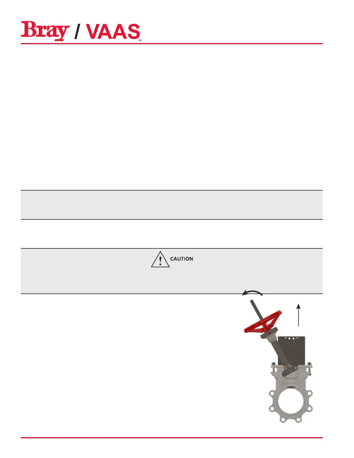
5. Remove one set of superstructure bolting and tilt the super structure to one side
as shown at right.
6. Lift the gate up until it fully clears the seat area and remove the old seat by tilt-
ing the top of the seat away from the body.
7. Insert the new seat with the bottom part first and lower the gate fully.
8. Bolt the super structure to the body again and then fasten the stem to gate
bolts.
 Loading...