EasyManua.ls Logo

Breezair IWC05 - User Manual

Breezair IWC05
8 pages
Print Icon
To Next Page IconTo Next Page
Loading...
®
Application
Notes
Application
Notes
Industrial Wall
Control (IWC05)
Question and Answer IconNeed help?

Do you have a question about the Breezair IWC05 and is the answer not in the manual?

Summary

Cable Lengths and Restrictions

Inputs and Outputs Overview

Control Modes: Local vs. External

Explains how the IWC05 controls the air cooler locally or via external devices.

System Output Capabilities

Details the IWC05's outputs for commanding external devices and providing status information.

Input Configuration and Functions

Remote OFF Input (Input 1)

Input 1 enables system power OFF when voltage is applied, indicated by 'R'.

Fan Speed Control Inputs (Inputs 2 & 3)

Inputs 2 & 3 control fan speed via binary coding for three distinct speed settings.

Pump ON;OFF Input (Input 4)

Input 4 enables pump operation, contingent on water level and cooler status.

Humidity Enable Input (Input 5)

Input 5 overrides external pump command if room humidity exceeds set point in EXTERNAL mode.

Pad Dry Time Input (Input 6)

Input 6 activates a 60-min fan run for pad drying in AUTO TIMER mode.

Humidity Disable Input (Input 7)

Input 7 disables humidity control in AUTO mode to prevent excessive temperature drops.

Spare Input (Input 8)

Input 8 is currently not assigned a specific function.

Output Configuration and Signals

System ON;OFF Output (Output 1)

Output 1 is activated when the Air Cooler is turned ON from any source.

Fan ON;OFF Output (Output 2)

Output 2 is activated whenever the air cooler fan has been turned ON.

Pump ON;OFF Output (Output 3)

Output 3 is activated whenever the air cooler pump has been turned ON.

External Control Output (Output 4)

Output 4 is activated whenever the air cooler is under external control.

Fault Output (Output 5)

Output 5 indicates when the air cooler is in a fault condition.

Serial Humidity Output (Output 6)

Output 6 provides binary humidity percentage data from the remote sensor.

Serial Temperature Output (Output 7)

Output 7 provides binary temperature data (°C) from the remote sensor.

Drain Control Output (Output 8)

Output 8 activates when the Drain Valve is open after a set time delay.

Temperature and Humidity Data Transmission

Humidity Bit Stream Format

Details the SLHDLHDL format for humidity data transmission.

Temperature Bit Stream Format

Details the SLHDLHDL format for temperature data transmission.

Bit Timing Specifications

Outlines timing parameters for start pulse, bits, pause, and update rates.

System Configuration and Cable Lengths

Input and Output Connection Diagrams

Illustrates the physical connections for inputs and outputs.

Master and Slave System Layouts

Diagrams showing system configurations with Master and Slave units and cable lengths.

Cable Specifications and Recommendations

Lists cable types, maximum lengths, and routing recommendations.

Fan Speeds and Airflow

External Mode Fan Speed Control

Describes the three fan speeds (MIN, MED, MAX) available in EXTERNAL mode.

Airflow Performance Curves

Presents performance curves for 'External' fan speed inputs.

Overview

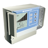
The Breezair Industrial Wall Control (IWC05) is a sophisticated device designed for both local and external control of Breezair evaporative air coolers equipped with the CPMD digital module. It facilitates integration with external systems such as PLCs (Programmable Logic Controllers) or Building Management Systems (BMS), offering comprehensive control and monitoring capabilities.

Function Description:

The IWC05 serves as an interface for managing air cooler operations. Locally, it provides automatic temperature and humidity control, water management, and auto-drain features in "AUTO" mode, along with manual control of cooler functions in "MANUAL" mode. When integrated with external devices, the IWC05 transitions to an "EXTERNAL" mode, where it exclusively responds to commands from the connected PLC or BMS, overriding its internal AUTO or MANUAL modes.

The device continuously provides outputs detailing the status of various air cooler components (fan, pump, drain valve) and the remote sensor's temperature and humidity values. These outputs can be utilized to command other external devices like dampers, fans, or signal equipment.

Important Technical Specifications:

Input Voltage:

The IWC05 accepts external input voltages ranging from 4VDC to 32VDC. Input current is limited by series resistors. All inputs are optically isolated from the main circuits, and the IWC05 does not have an internal power supply for external inputs.

Output Voltage:

It switches outputs ranging from 1.4VDC to 32VDC at a load of 40mA. Outputs 1, 2, 3, 4, 5, and 8 are switches that function when connected to an external power supply within this voltage range.

Cable Lengths:

The maximum total cable length between the cooler CPMD module and the Remote sensor (via the IWC05) is 100m. Within this limit, the maximum sensor cable length must not exceed 60m. For instance, a combination of 40m of communications cable and 60m of sensor cable is permitted, or 80m of communications cable and 20m of sensor cable. For distances greater than 100 meters between the IWC05 and a PLC or BMS, shielded cables are recommended to ensure signal integrity.

Cable Requirements for Longer Lengths:

If longer cables are used (beyond standard kit lengths), specific conditions must be met to avoid excessive voltage drop and electrical noise:

  • Cable conductors must be larger to reduce voltage drop.
  • Cables must be screened (or shielded) to reduce noise.
  • Screens must be earthed (grounded).
  • Conductors must be correctly orientated, using junction boxes or high-quality plugs for terminations.
  • Digital signal cables must not be installed next to power cables.

Input Configuration (External Mode):

In EXTERNAL mode, the power source for the IWC05 must be provided by an external adaptor (e.g., a common small appliance adaptor) adjacent to the Wall Control.

Usage Features:

Control Modes:

  • AUTO Mode: Provides automatic temperature and humidity control, water management, and auto-drain features using the supplied Remote Sensor.
  • MANUAL Mode: Allows manual control of cooler functions.
  • EXTERNAL Mode: The IWC05 responds solely to external commands from PLCs or BMS, overriding its internal AUTO or MANUAL modes. In this mode, temperature, humidity, and clock displays cycle every 5 seconds.

Input Functions:

  • Input 1 [Power] - Remote OFF: A positive voltage to this input holds the system in the OFF state, indicated by an 'R' on the IWC05 screen. This input is not recommended for emergency situations due to its fail-safe nature (a cut cable would prevent switching OFF).
  • Input 2 [F1] - Fan1 & Input 3 [F2] - Fan2: These inputs work in conjunction using a binary code to provide three fan speed settings (LOW, MED, HIGH) for the cooler fan.
    • No voltage on Input 2 or 3: Fan OFF.
    • Positive voltage on Input 2 only: LOW speed.
    • Positive voltage on Input 3 only: MED speed.
    • Positive voltage on both Input 2 and Input 3: HIGH speed.
  • Input 4 [Pump] - Pump ON / OFF: A positive voltage enables the pump. Pump operation is subject to the CPMD module and cooler status, meaning it won't run if there's insufficient water.
  • Input 5 [H.E.] - Humidity Enable: Functions only in EXTERNAL mode. It allows the IWC05 to override external pump commands and disallow the pump when room humidity is high, preventing further cooling if undesirable. If disabled, the pump runs regardless of room humidity.
  • Input 6 [DT] - Pad Dry Time: In AUTO TIMER mode, when the clock stops the cooler, the fan continues to run for 60 minutes on speed 2 to dry the cooling pads.
  • Input 7 [HD] - Humidity Disable: Disables humidity control in AUTO mode when no external control is present. This prevents the cooler from operating to raise indoor humidity if the temperature is satisfied but humidity falls below the set point, which would further lower room temperature.
  • Input 8 [Sp1] - Spare: Currently has no defined function.

Output Functions:

All outputs are indicators of the air cooler's state and are not monitored for integrity.

  • Output 1 [ON] - System ON / OFF: Activated when the air cooler is ON from any source or mode.
  • Output 2 [Fan] - Fan ON / OFF: Activated when the air cooler fan is ON.
  • Output 3 [Pump] - Pump ON / OFF: Activated when the air cooler pump is ON.
  • Output 4 [Ext] - External Control: Activated when the air cooler is under external control.
  • Output 5 [Fault] - Fault ON / OFF: Activated when the air cooler is in a fault condition. Refer to the Installation and Operation manual for fault details.
  • Output 6 [S.Hum] - Serial Humidity: Activated when the air cooler is ON or in Standby Mode. Provides humidity as a percentage in a binary bit stream.
    • Bit stream format: SLHDLHDL...HDLP (Start pulse, Low, High for synchronization, Data state, Pause).
    • Bit timing: Start pulse (750mSec on, 250mSec off), A High Bit (500mSec on, 250mSec off), A Low Bit (250mSec on, 500mSec off), Pause (1000mSec off).
    • Update Rate: 14 seconds.
    • Shift in PLC: LEFT.
  • Output 7 [S.Temp] - Serial Temperature: Activated when the air cooler is ON or in Standby Mode. Provides temperature (10 x Temperature in °C) in a binary bit stream.
    • Bit stream format and timing are identical to Serial Humidity.
  • Output 8 [Drain] Drain Control Output: Activated when the Drain Valve is open, only after a set time delay. It remains active while the valve is open. If the valve opens for less than the delay time, the signal remains active for 5 seconds.

Fan Speeds & Air Flow (External Mode):

When the wall control is NOT in EXTERNAL mode, the fan operates through 10 speeds based on automatic or manual settings. In EXTERNAL mode, the fan can only operate at three specific speeds:

  • MINIMUM: Speed 3
  • MEDIUM: Speed 6
  • MAXIMUM: Speed 10 Performance curves (Static Pressure vs. Airflow L/s) are provided for the Breezair TBA 550 cooler at these three speeds for integration with downstream systems.

Maintenance Features:

The manual emphasizes proper cable management and installation to ensure reliable operation and avoid malfunctions. It also highlights that Seeley International takes no responsibility for malfunctions if longer cables are used without adhering to the specified conditions. The product warranty may be voided if maximum data and sensor cable lengths are exceeded or cables are not routed according to recommendations. Regular routing of cables at least 300mm away from power cables and high-power machines, with right-angle crossings, is advised.

Breezair IWC05 Specifications

General IconGeneral
BrandBreezair
ModelIWC05
CategoryController
LanguageEnglish

Related product manuals