GB
3
OWNER'S MANUAL • PATH
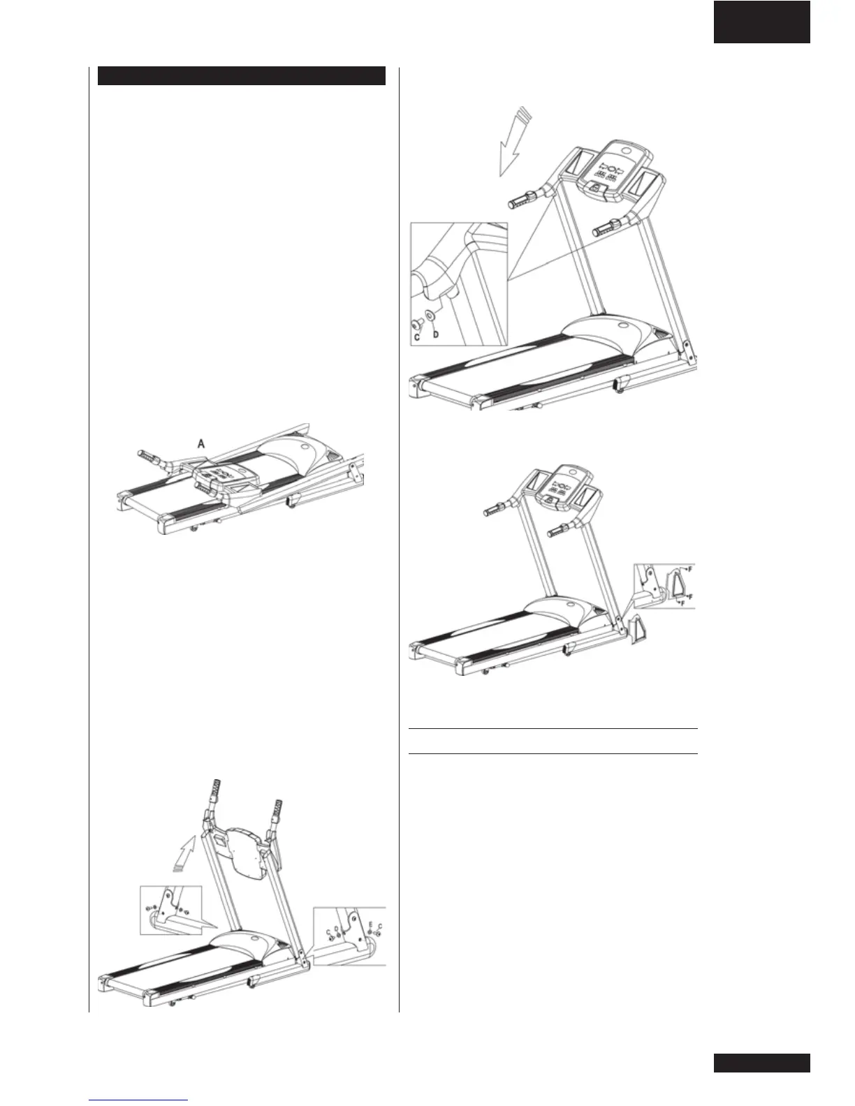
Put the console to the correct position. Tighten the
screws (C) and washers (D) inside holes at the top of
the upright.
Attach the side caps (B) with screws (F) at the
bottom of the upright, and tighten them well.
POWER CORD AND GROUNDING
INSTRUCTIONS
Plug the socket end of the power cord into the
treadmill at the left front corner. Before connecting
the device to a power source, make sure that local
voltage matches that indicated on the type plate.
The treadmill operates at 110 V or 230 V.
This treadmill must be grounded. If it should
malfunction or breakdown, grounding provides
a path of least resistance for electrical current to
reduce the risk of electrical shock. This product
is equipped with a cord having an equipment-
grounded conductor and a grounding plug.
The plug must be plugged into an appropriate
outlet that is properly installed and grounded in
accordance with all local codes and ordinances.
Do not use extension cables when connecting the
equipment to the power source.
ASSEMBLY
As for the assembly of the device, we recommend
two grown-up persons. Do not take the treadmill
out of the box: use the packing material to cover the
floor on the assembly site.
Before assembling the device, insure all parts are
present:
1. Frame
2. Power cord
3. Assembly kit: keep the assembly tools, as you may
need them e.g. for adjusting the equipment
In case of problems contact your Bremshey dealer.
The directions left, right, front and back are defined
as seen from the exercising position. To avoid
injury, you must fold up the deck prior to lifting the
treadmill out of the box.
Locate the hardware bag and parts that are listed in
the chart below.
Part# Description Q´TY
A Main frame and console 1
B Side cap 2
C Screw 6
D Washer 4
E Washer 2
F Screw 6
G Allen key 1
H Screwdriver 1
I Safety Key 1
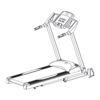
Lift up the upright, then place the screws (C) and
washers (D, E) inside holes at the bottom of the
upright. Tighten them well.