10
9.
Attach viewfinder bracket
(Abb. 9b). Locate the viewfinder bracket screws
(15, Fig. 1b and Fig. 9a) and remove the nuts from the screws. Slide
the holes in the viewfinder bracket over the viewfinder bracket screws.
Replace the nuts and tighten to a firm feel only.
9a. Attach viewfinder tube:. Back off the viewfinder collimation screws (5,
Fig. 1b) and slide the viewfinder tube into the bracket. Orient the view-
finder eyepiece as depicted in Fig. 1b. Tighten the collimation screws to
a firm feel. See Aligning the viewfinder, page 14.
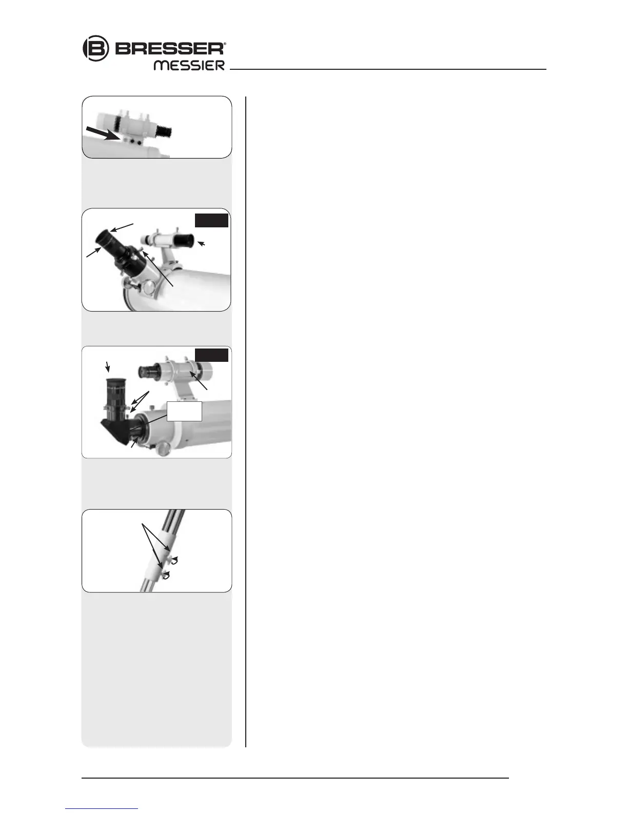
10. Insert the eyepiece: NT models (Fig. 10a): Lift to remove the dust cap
from the eyepiece holder on the focuser assembly. Set the dust cap
aside in a safe place and replace it when you have finished observing
to protect the eyepiece assembly. Back off the eyepiece thumbscrews
(1, Fig. 1a) and insert the supplied 25mm eyepiece (3, Fig. 1a) into the
the eyepiece holder. Tighten the holder thumbscrews to a firm feel to
secure the eyepiece. AR models (Abb. 10b): Lift to remove the dust cap
from the eyepiece holder on the focuser assembly. Set the dust cap
aside in a safe place and replace it when you have finished observing
to protect the eyepiece assembly. Back off the eyepiece thumbscrews
(1, Fig. 1b) and slide the diagonal prism into the holder and tighten the
thumbscrews to a firm feel only. Insert the supplied 25mm eyepiece (3,
Fig. 1b) into the the diagonal prism. Tighten the prism‘s thumbscrews to
a firm feel to secure the eyepiece.
11. Adjust the height of the tripod: Adjust the height of the tripod by
loosening the tripod lock knobs (Fig. 11). Extend the sliding inner
section of each tripod leg to the desired length; then tighten each knob.
Adjust the tripod to a height that is comfortable for viewing.
13. Remove Plastic from Reticle LED
*: The polar alignment reticle LED
(30, Fig. 1d) contains two watch batteries. The reticle‘s LED is shipped
with a plastic strip between the two batteries to protect battery life.
Unthread both the thumbscrew (F) and the threaded lid (E). Remove
the plastic strip before using. Refer to the reticle assembly in Fig. 13b
and note the orientation of the batteries. Place the batteries (C) into the
battery holder (D) before inserting into the reticle container (A).
NOTE:
The 2” focusers of the Messier Series from AR-102 or NT-130 on have a
built in extension tube. Depending on the accessories used, or when using
a camera, it might not be possible to reach the focus. Focus travel to the
inside might not be sufficient in the standard configuration. To reach focus,
unscrew the eyepiece holder, then the following 25mm extension tube.
Screw the eyepiece holder back in place.
Fig. 10b: Insert eyepiece into
diagonal prism and tighten
thumbscrews.
Eyepiece
Holder
Thumbscrews
Diagonal
prism
Viewfinder
AR
Fig. 10a: Insert eyepiece intor holder
and tighten thumbscrews.
Eyepiece
Holder
Thumbscrew
NT
Viewfinder
Fig. 11: Adjust the tripod height
using the leg lock knobs.
Leg lock knob
Fig. 9b: The finder scope assem-
bly has a dovetail bracket, that
fits the holder that is mounted on
the optical tube.
 Loading...