Document # 100452 RevK 6 Printed in USA © 2012
Note :
Some models may
not have a detachable
power cord.
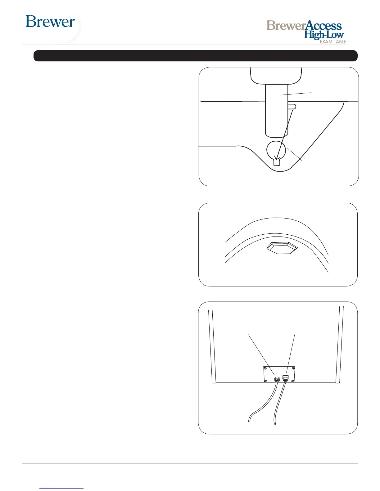
Figure 7. Power Cord and Foot Control
Foot Control Power Cord
Leveling the Table
A leveling screw pad (Figure 6) is located in six places
under the table’s base and rear cabinet. Adjust the six
leveling pads to achieve a solid, level installation.
Installing the Power Cord
(Models 6001, 6500 & 6501)
1. Remove the power cord from the shipping bag.
2. Insert the female plug end of the power cord into the
receptacle on the table (Figure 7). Make sure the tabs
are aligned and the plug is fully seated.
Note: The power cord is installed at the factory on model
6000.
Installing the Foot Control
1. Insert the male plug of the foot control cord into the
receptacle on the table (Figure 7). Make sure the pins
are properly orientated and the plug is fully seated.
2. Turn the locking ring clockwise to secure the plug to
the table.
Figure 6. Leveling Screw Pad (located under table)
INSTALLATION (continued)
Installing Grab Bars
1. Remove from drawer.
2. Grab bars t on either side.
3. Align pin on grab bar shaft with mating slot on side of
table. See Figure 5.
4. Push grab bar all the way down and rotate to front of
table.
5. Push grab bar down until it engages to prevent left or
right movement.
Grab Bar
Mounting Support
Figure 5.


 To Next Page