Document # 100452 RevK 5 Printed in USA © 2012
Overview
Perform the following sequence in order when setting up
the table:
- Uncrating
- Leveling the Base
- Installing Grab Bars
Uncrating
NOTE: Inspect all boxes and contents for damage. Re-
port any damage to the carrier immediately.
CAUTION
To avoid damaging the table’s upholstery or paint-
ed surfaces, DO NOT use a knife or other sharp
object to open the packaging. Also, to avoid dam-
aging the table lift only at points indicated in Figure
3. Do not lift at other points as indicated by the
note in Figure 4.
CAUTION
Do not plug power into table prior to removal of all
packaging materials.
1. Remove stretch wrap surrounding table.
2. Cut and remove banding and protective foam tube
attaching table to pallet.
3. Remove the 6 steel brackets securing the table to the
pallet, one at each of the four corners and one at the
middle on each side of the table. The brackets engage with
the table levelers to hold the table securely to the pallet.
Remove the 2 bolts from each bracket using a 7/16” socket
or wrench. Take care not to scratch the unit when turning
the wrench.
4. Remove the 2 screws attaching the spacers on either side
of the wooden U-shaped brace located under the front
corners of the cabinet. Remove the 2 screws attaching the
U-shaped brace tho the pallet.
5. Remove the foot control from the rear drawer. Insert the
foot control cord into the receptacle at the bottom of the
rear panel. Secure with locking ring.
6. Remove the gray power cord from the rear drawer. Plug the
power cord into the socket at the bottom of the rear panel.
Plug the power cord into a 120 Volt grounded receptacle.
7. Make sure the black On/Off Switch at the back of the table
is on.
8. Depress the switch on the foot control for lifting the seat
section until all the weight is removed from the wooden
U-shaped brace. Remove the brace and spacers.
9. Unplug the power cord from the table and the receptacle.
Remove the foot control from the table table. Slide the
table forward off the pallet.
• Caution: Do not lift table by stirrups. Lift front of table by leg
support. Pull leg support (not leg extension) out approximately
6”. Lift rear of table by pushing top rear pass-through drawer
to one side and using opening as a hand hold.
INSTALLATION
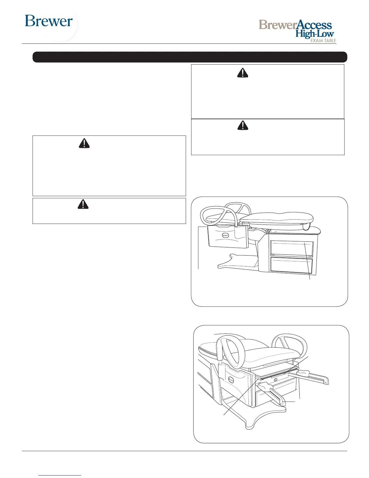
Figure 3. Table Lift Points
Lift table at these points only
Slide drawer and
lift here
Pull Leg Support out
slightly and lift here. Do not
lift by the Leg Extension.
See Figure 4.
WARNING
The table weighs approximately 395 lbs. Two or
more people should assist in removing the table
from the shipping skid. Also, use proper lifting
techniques when lifting. Failure to do so could
result in serious injury.
CAUTION
Do not use the stirrups to lift or move the table.
The Leg Support may be used to lift the table. Do
not pull on the Leg Support to slide the table.
8. The electrical rating for this unit is 115 VAC, 60 Hz,
5.8 amp maximum. The three-pronged grounding
plug on the table power cord must be plugged into
a matching three-pronged, grounded, non-isolated,
correctly polarized 115 VAC receptacle.
Figure 4. Stirrups & Treatment Pan
NOTE: DO NOT
LIFT HERE
Leg
Support
Do Not Use
Leg Extension
to Lift


 To Next Page
 Loading...