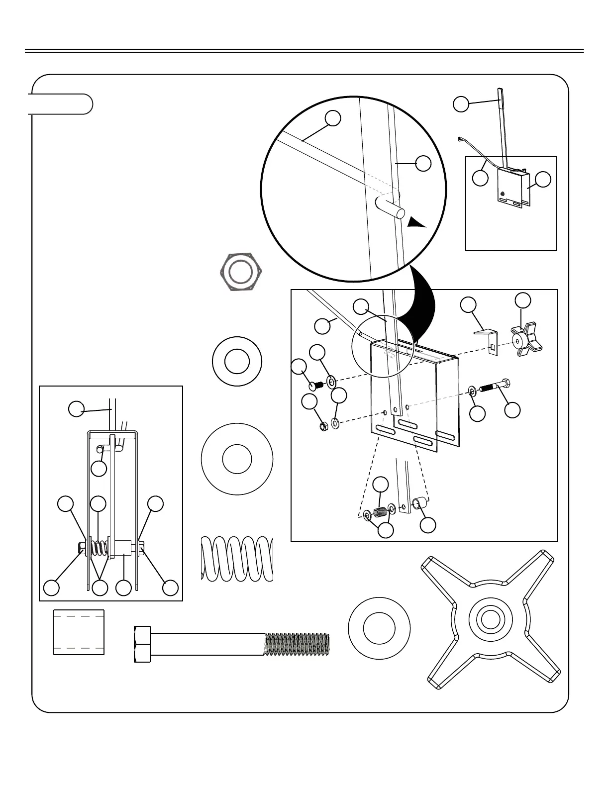
Figure 9.
ASSEMBLE GAGE PLATE
9a. Insert Stop Handle (31) through slot
opening at the top of the Gauge Plate
(11).
9b. Insert the ‘S’ shaped end of Link Rod
(12) through the upper hole of the
Flow Control Handle (31).
9c. Assemble Flow Control (31) to Gage
Plate (11) as shown, using hardware
provided:
• One 5/16”x2-3/4” Hex Bolt (36)
• Two 5/16” Flat Washers (32)
• One Latch Spacer (35)
• Two Special Washers (33)
• One Spring (34)
• One 5/1/6” Hex Nut (15)
Note: See graphic inset below for hard-
ware orientation.
9d. Attach Handle Stop (30) and Knob
(29) as shown, using hardware pro-
vided:
• One 5/16”x3/4” Carriage Bolt (41
• One Crvd Washer. (39).
9e. Slide Flat Grip (37) on end of Flow
control Handle (31).
34
Spring
Qty. 1
11
30
29
31
12
15
32
39
33
34
35
32
36
41
37
12
31
11
12
34
15
3232
3533 35
31
12
36
5/16”x2-1/4” Hex Bolt
Qty. 1
34
Washer Special
Qty. 2
32
Washer 5/16”
Qty. 2
39
Washer Crvd
Qty. 1
35
Spacer, Latch
Qty. 1
29
Knob 4-Prong
Qty. 1
15
Hex Nut 5/16”
Qty. 1