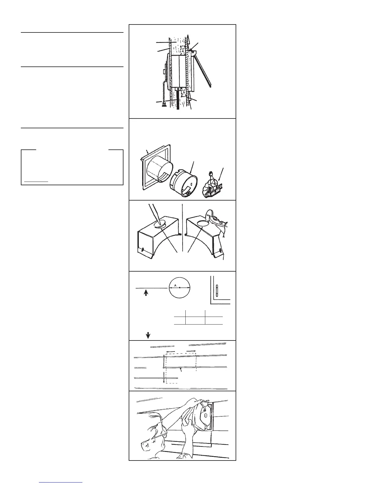
FIG. 2
FIG. 3
OUTER HOUSING
INNER
HOUSING
MOTOR
ASSEMBLY
NOTE
Remove bottom knockout
ONLY!
CENTER LOCATION FROM
INSIDE WALL
FIG. 4
5 FEET MINIMUM
ABOVE FLOOR
506 507
A 10-1/4" 8-1/4"
26,03 CM 20,95 CM
14-1/2"
36,83 CM
14-1/2"
36,83 CM
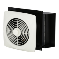
TYPICAL INSTALLATION
This unit mounts in walls 4-1/2” to 9-1/2” thick. Outside
housing flange is fastened to casing strips. If sheath-
ing behind siding is not wood, provide extra supports
between walls, nailed or screwed to siding. (FIG. 1)
PREPARE FAN
1. Remove motor assembly by loosening mounting
screws, rotating assembly, and lifting it out of inner
housing.
2. Use care when handling motor bracket assembly to
prevent damage to blade. Do not set down assembly
with weight of motor resting on the blade.
3. Pull inner housing out of outer housing. (FIG. 2)
4. Remove knockout from bottom of wiring box (pro-
vided in parts bag). (FIG. 3)
INSTALL FAN
5. From inside room, choose fan location. Make sure
that wall stud does not run through location. Lay out
housing opening on wall. (FIG. 4)
INSTALLER - PLEASE NOTE:
Center of housing opening must be a minimum
of 5 feet above the floor.
If fan will be installed higher than 5 feet above
the floor: Make sure that user(s) can comfort-
ably reach chain and can pull chain in and out
horizontally to operate.
6. Transfer center of circle to outside wall.
7. Cut out round hole on inside wall.
8. On outside wall, lay out 14-
1
/
2
” square around marked
center location. (FIG. 5)
9. Cut hole in siding only. DO NOT CUT SHEATHING.
Nail down all loose ends.(FIG. 6)
10. Cut round hole in sheathing.
11. Install 1” x 2” casing strips on side of square. (FIG. 7)
12. Measure wall thickness and remove appropriate
knockout(s). (FIG. 8)
13. Put large bead of caulk on inside of outer housing
flange. Insert outer housing into hole in outside wall
and use inner housing to test the fit.
14. Nail or screw outer housing to casing strips. Caulk
all around outside of flange and casing strips. Do
not fasten door closed.
15. Run wiring to installation location.
16. Remove chain and switch trigger from parts bag.
Thread chain through chain lock on inner housing
then through switch trigger, emboss on inner hous-
ing, and attach to clip on door of outer housing. (FIG.
9)
17. Insert inner housing into wall and pull wiring through
opening in housing. Use (3) black sheet metal
screws, provided in parts bag, to fasten housing
halves together. (FIG. 10)
18. Attach wiring to wiring box with proper type of con-
nector. (FIG. 10)
19. Make electrical connections to wiring box cover as
shown. Make sure unit is grounded using green
ground screw. Place wiring box into housing open-
ing and install wiring box cover with (2) sheet metal
screws provided in parts bag. (FIG. 10)
20. Insert tab on switch trigger into slot in wiring box
cover and place trigger over switch. (FIGS. 9 & 10)
21. Reinstall motor assembly and tighten screws
securely. Plug motor into receptacle on wiring box
cover. Spin blade by hand to check clearance.
22. Thread chain through grille so it passes over wear
plate.
23. Fasten grille to motor bracket with grille stud and
knob from parts bag.
24. Turn on power and check operation of fan.
FIG. 6
FIG. 1
WALL STUD
ELECTRICAL
WIRING
ADD SUPPORT IF
SHEATHING IS NOT
WOOD
CASING STRIPS
2
FIG. 5
WALL BOARD
 Loading...