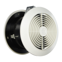
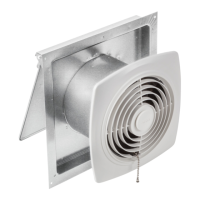
MODEL 512
ROOM TO ROOM FAN
FIG. 1
SWITCH OR
SPEED
CONTROL
WALL OUTLET
FAN
FIG. 2
FIG. 3
MOUNTING
BRACKET
FIG. 4
MOUNTING
BRACKET
FIG. 5
GRILLE
BRACKET TAB
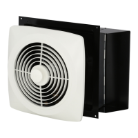
FAN HOUSING
AIRFLOW DIRECTION
(INLET)
FAN HOUSING FLANGE
WIRING BOX
GREEN OR BARE
WIRE
WHITE WIRES
COVER
FAN
HOUSING
BLACK
WIRES
FAN HOUSING
WIRING BOX
GRILLE
FAN HOUSING
PANELING
PANELADO
WALL
3,2 - 6,3 mm
1
/
8
” -
1
/
4
”
FRAME
READ AND SAVE
THESE INSTRUCTIONS
WARNING
TO REDUCE THE RISK OF FIRE, ELECTRIC
SHOCK, OR INJURY TO PERSONS, OBSERVE THE
FOLLOWING:
1. Use this unit only in the manner intended by the
manufacturer. If you have questions, contact the
manufacturer at the address or telephone number
listed in the warranty.
2. Before servicing or cleaning unit, switch power off
at service panel and lock the service disconnect-
ing means to prevent power from being switched
on accidentally. When the service disconnecting
means cannot be locked, securely fasten a promi-
nent warning device, such as a tag, to the service
panel.
3. Installation work and electrical wiring must be done
by a qualified person(s) in accordance with all ap-
plicable codes and standards, including fire-rated
construction codes and standards.
4. Sufficient air is needed for proper combustion and
exhausting of gases through the flue (chimney) of
fuel burning equipment to prevent backdrafting.
Follow the heating equipment manufacturer’s
guideline and safety standards such as those pub-
lished by the National Fire Protection Association
(NFPA), and the American Society for Heating,
Refrigeration and Air Conditioning Engineers
(ASHRAE), and the local code authorities.
5. When cutting or drilling into wall or ceiling, do not
damage electrical wiring and other hidden utilities.
6. DO NOT CREATE AN OPENING IN A FIRE-
RATED WALL TO INSTALL THIS FAN. It is not an
exhaust fan, rather it is intended to direct air from
one room to another.
7. This unit must be grounded.
CAUTION
1. For general ventilating use only. Do not use to
exhaust hazardous or explosive materials and va-
pors.
2. To avoid motor bearing damage and noisy and/or
unbalanced impellers, keep drywall spray, con-
struction dust, etc. off power unit.
3. Please read specification label on product for fur-
ther information and requirements.
TOOLS AND
MATERIALS REQUIRED
❏ Pencil and ruler or tape measure
❏ Straight-blade screwdriver
❏ 3/16” drill bit
❏ Drill, electric or ratchet drive
❏ Pliers
❏ Drywall saw or saber saw
❏ Electrical supplies of type to comply with local
codes
INSTALL THE FAN
1. Plan installation. Fan will install in walls up to
5–1/8” thick. For wall less than 4–1/2” thick, a trim
board frame for spacing is required (see Step 13).
Fan can be controlled by a wall switch or speed
control (available separately).
2. Carefully cut out fan openings and switch box open-
ing. (FIG. 1)
CAUTION: BE SURE TO MEASURE AND MARK
CENTER OF FAN OPENING ON OPPOSITE WALL
BEFORE CUTTING OUT EITHER OPENING.
WARNING: WHEN CUTTING OR DRILLING INTO
WALL, BE CAREFUL NOT TO CUT EXISTING ELEC-
TRICAL WIRING.
FIG. 6
PLASTER
WALL
PARED
WALL
PARED
FAN
HOUSING
GRILLE
BRACKET
SOPORTE
INSTALLER: Leave This Manual With The Homeowner. HOMEOWNER: Use and Care Information on Page 2.