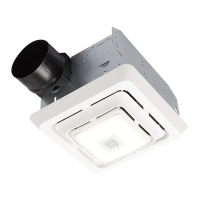
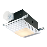
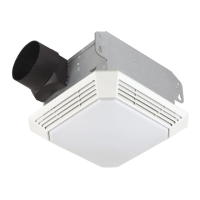
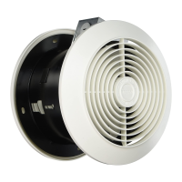
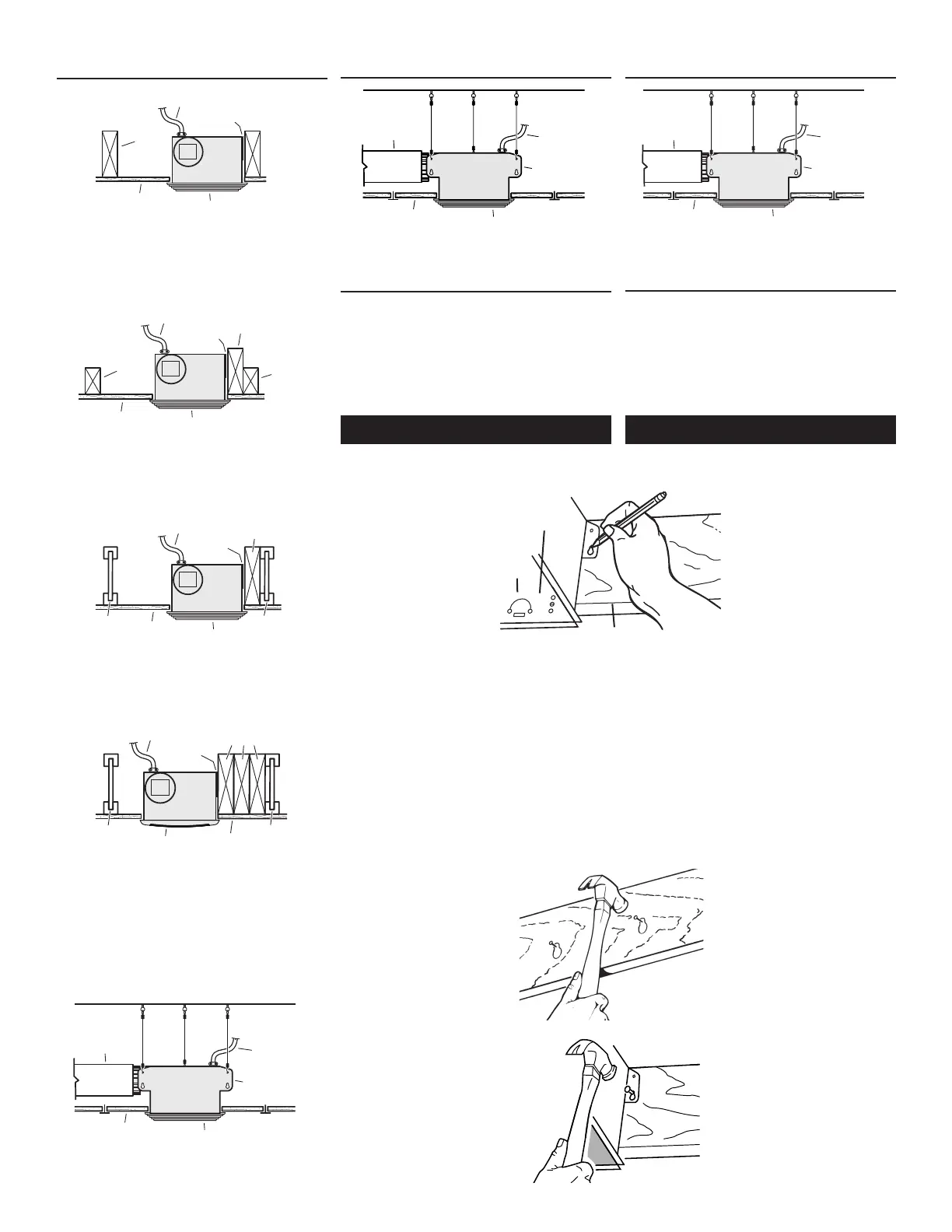
TYPICAL INSTALLATIONS
MOUNTING
TAB
GRILLE
SUSPENDED
CEILING MATERIAL
POWER
CABLE
4" ROUND
DUCT
HOUSING
SUSPENDED CEILINGS
Housing hung with wires - 3-point mount.
INSTALACIONES TÍPICAS
ALETA DE
MONTAJE
REJILLA
MATERIAL DEL
TECHO SUSPENDIDO
CABLE
DE ALIMENTACIÓN
CONDUCTO
REDONDO DE
4" (10.2 CM)
CUBIERTA
TECHOS SUSPENDIDOS
Cubierta montada con cables. Montaje de tres puntos.
INSTALL THE HOUSING
- PLEASE NOTE -
THE FOLLOWING INSTALLATION ILLUSTRATIONS
SHOW 2 X 6 JOISTS OR STUDS. IF YOU HAVE A
TRUSS OR “I”-JOIST INSTALLATION, MOUNT THE
VENTILATOR TO THE ADDITIONAL FRAMING IN
THE SAME MANNER. (Additional framing must
be a 2x6 (minimum height).
1. Choose the location for your fan in the ceil-
ing or wall. For best possible performance,
use the shortest possible duct run and a
minimum number of
elbows.
2. Position mounting
brackets against joist
or stud so that bottom
edge of housing will
be flush with finished
ceiling or wall.
Additional positioning
feature for 5/8”, 1”, &
1-1/4” thick ceiling or
wall material:
Holes in corners of housing are labeled with
various ceiling or wall material thicknesses.
Position housing so bottom edge of joist is
visible through a matched set of holes. The
housing is now in the proper position for that
ceiling or wall material thickness.
Additional positioning feature for 1/2” thick
ceiling or wall material:
Bend two tabs, on side of housing,
90
0
outward.
Lift housing until tabs contact underside of
joist or stud.
Mark the keyhole slot on both mounting
brackets.
New Construction
TAB
ALETA
HOLES
OROFICIOS
BOTTOM EDGE OF JOIST
BORDE INFERIOR DE LA VIGUETA
3. Set housing aside and
drive nails partially into
joist or stud at the top of
both keyhole marks.
4. Hang housing from nails
and pound nails tight.
To ensure a noise-free
mount, pound another
nail through the top hole
of each mounting tab.
INSTALACIÓN DE LA CUBIERTA
- POR FAVOR NOTE -
LAS SIGUIENTES ILUSTRACIONES DE LA INSTALACIÓN
MUESTRAN VIGUETAS O MONTANTES DE 2 X 6. SI LA
INSTALACIÓN ES EN UNA VIGA O EN UNA VIGUETA
EN “I”, MONTE EL VENTILADOR EN LA ESTRUCTURA
ADICIONAL DE LA MISMA MANERA. (La estructura
adicional debe ser un tramo de 2x6 (altura mínima).
1. Seleccione la ubicación del ventilador con lámpara en
el cielo raso o pared. Para obtener el mejor rendimien-
to posible, utilice un tramo de conductos lo más corto
posible y un número mínimo de codos.
Construcción nueva
2. Coloque las abrazaderas de
montaje contra la vigueta o
montante, de manera que el
borde inferior de la cubierta
quede al ras del cielo raso o
pared terminado.
Característica adicional para la
colocación en material de cielo
raso o pared de 5/8” (1.6 cm),
1” (2.5 cm) y 1 ¼” (3.2 cm):
Los orificios que se encuentran
3. Coloque la cubierta a un lado
e introduzca parcialmente los
clavos en la vigueta o mon-
tante, en la parte superior de
ambas marcas de los orificios
en forma de cerradura.
4. Suspenda la cubierta con
los clavos e introduzca los
clavos completamente. Para
asegurar un montaje sin
ruido, coloque otro clavo en el
orificio superior de cada aleta
de montaje.
Construcción nueva
en las esquinas de la cubierta están marcados con varios
espesores del material del cielo raso o pared. Coloque la
cubierta de manera que el borde inferior de la vigueta sea
visible a través del conjunto de orificios que coinciden.
Ahora la cubierta se encuentra en la posición adecuada
para ese espesor del material del cielo raso o pared.
Característica adicional para la colocación en material
de cielo raso o pared de ½” (1.3 cm):
Doble a 90º y hacia afuera las dos aletas que se encuen-
tran a los costados de la cubierta. Levante la cubierta
hasta que las aletas entren en contacto con la cara
inferior de la vigueta or montante.
Marque el orificio con forma de cerradura de ambas
abrazaderas de montaje.
2
ALETA DE
MONTAJE
REJILLA
MATERIAL DEL
TECHO SUSPENDIDO
CABLE
DE ALIMENTACIÓN
CONDUCTO
REDONDO DE
4" (10.2 CM)
CUBIERTA
TECHOS SUSPENDIDOS
Cubierta montada con cables. Montaje de tres puntos.
INSTALACIONES TÍPICAS
CUBIERTA
VIGUETA
DEL
TECHO
O PARED
ALETAS DE
MONTAJE
REJILLA
MATERIAL DEL
TECHO O PARED
CABLE
DE ALIMENTACIÓN
CUBIERTA MONTADA
DIRECTAMENTE EN LA VIGUETA
2x6 (o más grande). Descarga paralela a las viguetas.
CUBIERTA MONTADA EN UNA VIGA DE 2x4
Se requiere una estructura adicional para las aletas
de montaje. Descarga paralela a las viguetas.
CUBIERTA MONTADA EN UNA VIGUETA “I”
Se requiere una estructura adicional para las aletas
de montaje. Descarga paralela a las viguetas.
* La estructura adicional debe ser un tramo de 2x6
(altura mínima).
CUBIERTA
ALETAS DE
MONTAJE
REJILLA
MATERIAL
DEL TECHO
CABLE
DE ALIMENTACIÓN
ESTRUCTURA
ADICIONAL*
VIGUETA O
VIGA DE
2x4 DE
CIELO
RASO
VIGUETA O
VIGA DE
2x4 DE
CIELO
RASO
CUBIERTA
CABLE DE ALIMENTACIÓN
VIGUETA
"
I
"
ALETAS DE
MONTAJE
MATERIAL
DE CIELO RASO
ESTRUCTURA
ADICIONAL
REJILLA
VIGUETA
"
I
"
CUBIERTA MONTADA EN CUALQUIER
LUGAR ENTRE LAS VIGUETAS
Se requiere una estructura adicional
para las aletas de montaje.
CUBIERTA
CABLE DE ALIMENTACIÓN
VIGUETA
"
I"
ALETAS DE
MONTAJE
MATERIAL
DEL TECHO
ESTRUCTURA
ADICIONAL*
REJILLA
VIGUETA
"
I"
*
*
*
 Loading...