32
7 CHANNELING SYSTEM
Below is detailed the operation of the air distribution system to other adjacent or upper rooms of the stoves or inserts including this system.
7.1 STOVE MOD. ALICIA EXTRA
Model Alicia Extra includes on the rear top side two outputs with a 80 mm diameter corresponding to the forced air output channelling system
to heat other adjacent or upper rooms. It will be enough knocking softly the cover that is partially pierced and connect the ducts to the smoke
duct of the extractor on the stove. It is recommended use isolated duct of interior diameter 80 mm. The maximum distance of channelling is 9
meters.
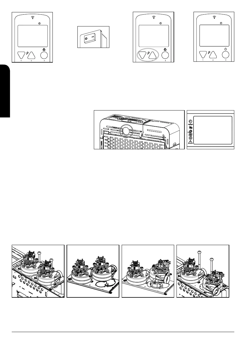
The regulation of the channelling system is made
by the electronic system of the stove, therefore
you can choose the operation of the channelling
by selecting the power level desired for each fan
regardless of the working power of the stove. To
do this you have to access to menu 1 and choose
the fan activation and the working power (see
drawing D26). Fan number 3 in these models is not
available.
7.2 INSERT MODEL NEVA EXTRA
The model Neva-Extra incorporates on the right side an outlet of diameter 80 which corresponds to the outlet for the forced ducted air to heat
an adjacent or top room. It is recommended use isolated duct of interior diameter 80 mm. The maximum distance of channelling is 9 meters.
The regulation of the channelling system is made by the electronic system of the stove, therefore you can choose the operation of the
channelling by selecting the power level desired for each fan regardless of the working power of the stove. To do this you have to access to
menu 1 and choose the fan activation and the working power. Fan number 3 in these models is not available.
7.3 STOVE 12 KW (MOD. CLARA EXTRA, CLEO EXTRA AND OLIVIA EXTRA)
The models Clara, Cleo and Olivia Extra include two outputs with a 80 mm diameter corresponding to the forced air output channelling
system to heat other adjacent or upper rooms. One of these outputs will always be placed on the rear of the stove. However, the other output
can be address to the rear or the right side, depending on our interest. To do this, it is necessary to change the position of the fan by following
the next steps:
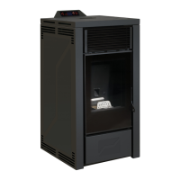
- Unscrew and remove the ceiling of the stove.
- Unscrew and remove the turbine or air extractor. See drawing D27
- Unscrew the base where the turbine or extractor rests. See drawing D28
- Turn the base to the lateral canalisation and screw again. See drawing D29.
- Place again the turbine or extractor in the lateral position. See drawing D30
- Place and screw again the roof of the stove.
D27 D28 D29 D30
The regulation of the channelling system is made by the electronic system of the stove, therefore you can choose the operation of the
channelling by selecting the power level desired for each fan regardless of the working power of the stove. To do this you have to access to
menu 1 and choose the fan activation and the working power (see drawing D31).
MENU
CERCA
CAMPO
D22
D23
MENU
SEGLI
UNITA
01
D24
MENU
08:53
31.0 ºC P-1
APAGADO
D25
Menú 01
VENT-2 1
D26
INSTALLATION, OPERATING AND SERVICING INSTRUCTIONS RADIOFREQUENCY SERIES
EN