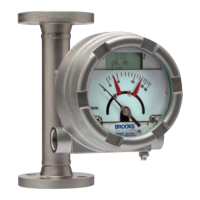
Installation and Operation Manual
X-VA-MT3809G-MT3810G-eng
Part Number: 541B182AAG
December, 2014
Models MT3809G & MT3810G
Contents
ii
Figures
Figure Page
Number Number
1-1 Model MT3809 and MT3810 Dimensional Drawings (mm/in) and weights (kg/lbs) -
General Purpose Housing ............................................................................................................. 1-6
1-2 Model MT3809 and MT3810 Dimensional Drawings (mm/in) and weights (kg/lbs) -
Intrinsically Safe Housing .............................................................................................................. 1-7
1-3 Model MT3809 and MT3810 Dimensional Drawings (mm/in) and weights (kg/lbs) -
Explosion Proof Housing ............................................................................................................... 1-8
1-4A Wiring Diagram, Model MT3809, 4-20 mA Transmitter ................................................................ 1-17
1-4B Wiring Diagram, Model MT3809, 4-20 mA Transmitter ................................................................ 1-18
1-5A Wiring Diagram, Model MT3809, 4-20 mA Transmitter, One or Two Optical
Alarms and PPU ............................................................................................................................ 1-19
1-5B Wiring Diagram, Model MT3809, 4-20 mA Transmitter, One or Two Optical
Alarms and PPU ............................................................................................................................ 1-20
1-6A Wiring Diagram, Model MT3809 Explosion Proof, 4-20 mA Transmitter with Inductive Alarms,
Optical Alarms and PPU................................................................................................................ 1-21
1-6B Wiring Diagram, Model MT3809 Explosion Proof, 4-20 mA Transmitter with Inductive Alarms,
Optical Alarms and PPU ............................................................................................................. 1-22
1-7A Wiring Diagram, Model MT3809, One or Two Inductive Alarms ................................................. 1-23
1-7B Wiring Diagram, Model MT3809, One or Two Inductive Alarms ................................................. 1-24
1-8A Wiring Diagram, Model MT3809, 4-20 mA Transmitter, One or Two Inductive Alarms .............. 1-25
1-8B Wiring Diagram, Model MT3809, 4-20 mA Transmitter, One or Two Inductive Alarms .............. 1-26
1-9A Power Supply vs. Maximum Load Resistance ............................................................................ 1-27
1-9B Cam Setting for Alarm Signal...................................................................................................... 1-27
2-1 Typical Bypass Installation .......................................................................................................... 2-3
3-1 Model MT3809 Electronics Basic Setup Menu Tree ................................................................... 3-3
3-2 Model MT3809 Electronics Detailed Setup Menu Tree ............................................................... 3-4
3-3 Model MT3809 Electronics LOI Chart Menu ............................................................................... 3-6
4-1
Exploded View, Model MT3809G and MT3810G - Gas Service ...................................................
4-5
4-2
Exploded View, Model MT3809G and MT3810G - Liquid Service ................................................
4-6
4-3
Exploded View, Model MT3809G, Size 15 (Gas or Liquid Service Only) ......................................
4-7
4-4
Exploded View, Model MT3809G, Size 16 (Liquid Service Only)..................................................
4-7
4-5
Meter Float Replacement & Cleaning (ETFE Option) ...................................................................
4-8
Table
Number
1-1 Specifications Meter ...................................................................................................................... 1-2
1-2A Model MT3809/MT3810 Capacities, Pressure Drop and Viscosity Immunity Ceiling ................... 1-3
1-2B Model MT3809 ETFE Lined Capacities, Pressure Drop and Viscosity Immunity Ceiling ............. 1-3
1-3A Model MT3809/MT3810 Pressure Ratings, Flanged .................................................................... 1-4
1-3B Model MT3809/MT3810 Pressure Ratings, NPT Female ............................................................. 1-4
1-3C Model MT3809/MT3810 Pressure Ratings, NPT Male ................................................................. 1-5
1-4 Temperature Cut-off Tables .......................................................................................................... 1-5
1-5 Approval Certificates ..................................................................................................................... 1-10
1-6 Hazardous Location Certification: Flame Proof (Exd) .......................................................................... 1-10
1-7 Process and Ambient Temperature Limits: Flame Proof (Exd) ............................................................. 1-10
1-8 Hazardous Location Certification: Intrinsic Safety (ia) / Non-sparking (nA) ............................................. 1-11
1-9 Process and Ambient Temperature Limits: Intrinsic Safety (ia) / Non-sparking (nA) ............................... 1-13
2-1 Maximum Torques Model MT3809 ETFE ..................................................................................... 2-4

 Loading...