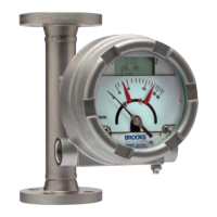
Installation and Operation Manual
X-VA-MT3809G-MT3810G-eng
Part Number: 541B182AAG
December, 2014
Models MT3809G & MT3810G
Contents
i
Section 1 Introduction
1-1 Description .................................................................................................................................... 1-1
1-2 Design Features ............................................................................................................................ 1-1
1-3 Meter Specifications ...................................................................................................................... 1-1
1-4 Optional Accessories.................................................................................................................... 1-9
1-5 Optional Electronic Equipment ...................................................................................................... 1-9
1-5-1 Transmitter with or without Alarms Display and Pulse Output ...................................................... 1-9
1-5-2 Inductive Alarms ............................................................................................................................ 1-14
1-5-3 Microprocessor Transmitter with or without Inductive Alarms....................................................... 1-16
Section 2 Installation
2-1 General.......................................................................................................................................... 2-1
2-2 Receipt of Equipment .................................................................................................................... 2-1
2-3 Recommended Storage Practices ................................................................................................ 2-1
2-4 Return Shipment ........................................................................................................................... 2-2
2-5 Installation of Flowmeter ............................................................................................................... 2-2
2-5-1 Installation and Maximum Torques of Model MT3809 ETFE........................................................ 2-4
2-6 Installation of the Model MT3809 Flowmeter with a Transmitter with or without Optional Alarms
and Pulse Output........................................................................................................................... 2-4
2-7 Installation of the Model MT3809 Flowmeter with a Transmitter with Inductive Alarms
(1 or 2 switches) ............................................................................................................................ 2-7
2-8 Installation of the Model MT3809 Flowmeter with Inductive Alarms (1 or 2 switches) .................. 2-7
2-9 Installation of the Model MT3809 Flowmeter with Transmitter and Digital Display and
Inductive Alarms ............................................................................................................................ 2-11
Section 3 Operation
3-1 Pre-start Check ............................................................................................................................. 3-1
3-2 Start-up and Operation of Flowmeter ............................................................................................ 3-1
3-3 Operation of the Model MT3809 Flowmeter with a Transmitter with or without Optional
Alarms and Pulse Output for Totalization...................................................................................... 3-2
3-4 Operation of the Model MT3809 Flowmeter with a Transmitter and
Inductive Alarms (1 or 2 switches) ................................................................................................. 3-7
3-5 Operation of the Model MT3809 Flowmeter with a Transmitter and Display ................................ 3-7
3-6 Operation of the Model MT3809 Flowmeter with Inductive Alarms (1 or 2 switches) ................... 3-7
Section 4 Maintenance
4-1 General Service Information.......................................................................................................... 4-1
4-2 Meter Float Replacement and Cleaning (MT3809 & MT3810) ..................................................... 4-2
4-3 Meter Float Replacement and Cleaning (MT3809 ETFE Option) ................................................. 4-5
4-4 Meter Indicator Reference Mark (Zero) Adjustment...................................................................... 4-5
4-5 Transmitter Replacement with or without Alarms and Pulse Output............................................. 4-5
4-6 Inductive Alarm Replacement ....................................................................................................... 4-5
4-7 Transmitter Replacement with Inductive Alarms........................................................................... 4-6
4-8 Monitoring the Integrity of the Transmitter Electronics - Diagnostic Alarms ................................. 4-6
4-9 Digital Display Replacement ......................................................................................................... 4-6
Section A Essential Instructions.......................................................................................................................A-1
Warranty, Local Sales/Service Contact Information..............................................................................Back Cover
Paragraph Page
Number Number

 Loading...