CONVERSION PARTS SET 1
La instalación de las partes sólo debe ser realizada por técnicos calificados.
Desconectar el interruptor principal y desconectar el cable de alimentación antes de cambiar las piezas
calibradas, de lo contrario la máquina podría comenzar a funcionar si por descuido se pisara el pedal, lo
que podría resultar en heridas.
* Al usar un motor con embrague, como resultado de la inercia el motor continuará girando después de
desconectar el interruptor principal. Se debe esperar hasta que el motor se haya detenido completamente
antes de comenzar a trabajar.
Die Teile dürfen nur von einem qualifizierten Fachmann installiert werden.
Vor dem Austauschen muß der Netzschalter ausgeschaltet und das Netzkabel aus der Steckdose gezogen
werden, weil sonst durch eine unbeabsichigte Betätigung des Pedals die Maschine in Gang gesetzt und
Verletzungen verursachen kann.
* Bei Verwendung eines Kupplungsmotors dreht sich der Motor wegen der Trägheit auch nach dem
Ausschalten weiter. Warten Sie deshalb bis der Motor zum vollständigen Stillstand gekommen ist, bevor
Sie zu arbeiten beginnen.
Installation of parts should only be carried out by a qualified technician.
Turn off the power switch and disconnect the power cord before replacing the gauge parts, otherwise the
machine will operate if the treadle is pressed by mistake, which could result in injury.
* When using a clutch motor, the motor will keep turning even after the power is switched off as a result of
the motor's inertia. Wait until the motor stops fully before starting work.
L'installation des pièces doit être confiée à un technicien qualifié uniquement.
Couper l'alimentation électrique et débrancher le cordon d'alimentation avant de remplacer les jauges,
sinon la machine risquera de se mettre en marche si on enfonce accidentellement la pédale, et donc de
causer des blessures.
* Lorsqu'on utilise un moteur à embrayage, le moteur continuera de tourner même après qu'on ait coupé
l'alimentation électrique en raison de l'inertie du moteur. Attendre que le moteur se soit complètement
arrêté avant de commencer le travail.
CAUTION/ACHTUNG/ATTENTION/ATENCION
INSTRUCTION MANUAL
BEDIENUNGSANLEITUNG
MANUEL D’INSTRUCTIONS
MANUAL DE INSTRUCCIONES
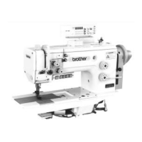
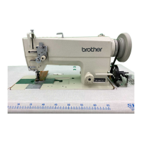
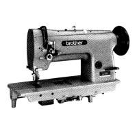
LS2-B891
CONVERSION PARTS SET (SINGLE NEEDLE TO TWIN NEEDLE)
UMRÜSTUNGSSATZ (VON EINZEL-AUF DOPPELNADEL)
JEU DE PIECES DE CONVERSION (AIGUILLE SIMPLE A AIGUILLE DOUBLE)
JUEGO DE PIEZAS DE CONVERSION (UNA SOLA AGUJA A DOS AGUJAS)
■ Installation ■ Montage ■ Installation ■ Instalacion