Do you have a question about the Bruderer BBV 190 Series and is the answer not in the manual?
Remove the guard plate part number 12206.00.0.00.
Remove the cover sheet from the machine.
Set the feed length to its maximum value.
Turn off or disconnect the oil pump.
Jump the oil pressure switch if it is necessary for the procedure.
Set the selector switch to the 'break open' position for manual turning.
Perform the disassembly of the clamping bar.
Turn the eccentric shaft to access the roller clamping screws.
Position the machine to the Bottom Dead Center (BDC).
Install the tension bracket and lower feed roller without tightening screws.
Ensure the feed roller is correctly aligned with the clamping bar.
Adjust the feed roller horizontally at BDC or TDC position.
Measure the distance from roller ends to the housing base.
Tighten screws with Loctite 243 to a torque of 14Nm.
Turn the machine to position the lower feed roller vertically.
Install the upper feed roller at the roller shaft without tightening.
Verify the upper feed roller end matches the lower feed roller end.
Tighten the upper feed roller screws with Loctite 243 and torque.
Compensate screw play to the back for later clamping bar adjustment.
Set the material thickness scale to the zero position.
Remove the plug screw with designation M14x1,5.
Set the feeding length to 20mm.
Set the spring force of the roller press springs to 10mm.
Use a steel bolt to position the feeder, finding the hose connector.
Set the control valve to 'feeding without roller lifting'.
Ensure lifter spindles do not lean on lifter seats to prevent misadjustment.
Set the control valve to the 'open' position.
Insert 0.02mm thick foils under the feed rollers on both sides.
Insert 0.02mm thick foils between the clamping bar and strip feeding table.
Set the control valve to feeding without roller lifting position.
Fix foils between feed rollers, ensure foils under clamping bar are loose.
Tap the clamping bar to fix foils, ensuring they cannot be pulled out.
Turn strip thickness adjustment clockwise to lift the clamping bar.
Turn strip thickness adjustment counter-clockwise to free the foils.
Fix the clamping bar with M6x40 screws using Loctite 243 and 9Nm torque.
Adjust strip thickness to center markings, ensuring all four foils are fixed.
Set the strip thickness scale part number 12234.00.1.00 to Zero.
Replace mounting bolts with a plug screw and copper ring.
Insert foils, set control valve, and turn the machine to check operation.
Mount the guard sheet part number 12206.00.0.00 again.
Turn on and reconnect the oil pump.
Set the control valve to 'semi-lifting' position.
Press the piston by hand until it reaches the limit stop.
Open the adjusting screw until there is no pressure on the limit stop.
Close the adjusting screw by half a rotation to create light pressure.
Set the control lever to 'feeding with roller lifting' position.
Bring the press to BDC position, measuring with a dial gauge.
Loosen pin screws if tappet pins are not free, then restart.
Turn the tappet pin screw clockwise to move the dial gauge for 0.01mm tension.
Counter the tappet pin screw using the hexagonal nut.
Repeat the tappet pin adjustment procedure for the second tappet pin.
Check the pilot release function using two 0.02mm shims.
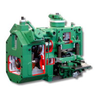
| Brand | Bruderer |
|---|---|
| Model | BBV 190 Series |
| Category | Industrial Equipment |
| Language | English |