In
BROEL &
KJA::R
Nrerum
-
Denmark
I
I
I
I
I
I
I
lzl
Modulation Frequency
Hz
tuning
On
Technical Description
1023.1
~
_________________________
~
0032
-,
Var.
Osc.
I
Z40
taZOO
kHz
Tl
..---------_01.1/5
;-
_____
.oIB;:..Z'---+-+o
modulation
Out
JZ
H2
FAZ
PZ-
-
--02
fva-;:-20-22Ok~~n-;3Vp-::p-
C2
Frequency Counter
ffix
10
kHz
TTL
-"---------'
Lin
Turn
Off
120
kHz
sine
Lo
g
240
to
200kHz
TTL
Lin:0,5mV/Hz
Otal0V
Log:
IV/Octave
-1
to
10V
~
~
__
. _ _
~O
2..
__
AA
3
_________
_
Compressor
General
I
I
I
---------
Off
Z 3
+15,4
v----f]
Off
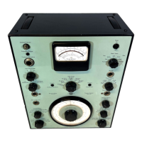
Generator
The Sine
Generator
Type
1023
is a high
quality
signal source
which
covers a frequency range from
10Hz
to
20
kHz.
The
output
signal is produced by mixing a Fixed Oscillator Signal
of
120
kHz
with
a Variable Oscillator signal
of
240
to
200
kHz divided by
2.
The Fixed
Oscillator
signal is produced by a
4,88
MHz Crystal Oscillator
which
is divided by 61 and by 2 and
multiplied
by 3
after
which
the
120
kHz
signal
is applied to the Compressor
Amplifier
where
the ampli-
tude
of
the
signal is controlled by a
DC
voltage proportional
to
the Com-
pressor
input
signal.
The Variable signal is created by a Voltage Controlled Oscillator
with
a
frequency range
of
1,2
to
1 MHz
which
is divided by 5. In order
to
linear-
ize and stabilize the
VCO, an
error
feed-back
arrangement
has been
made as explained
later
in the description.
The Variable
Oscillator signal can have a
linear
or a logarithmic relation-
ship to
the
DC
tuning
voltage of 0
to
10V.
III Lin. mode the tuning
voltage is
0,5
mV
per Hz and in Log mode 1 V per octave
with
OV
at
20
Hz
and
thus
-1
V at
10Hz.
The
output
signal of the Generator can be modulated by applying a pul-
sating
DC
voltage to the VCO.
Modulation
frequencies
of
1 -
2,5
-
6,3
and
16
Hz
can be selected
while
the
frequency deviation is ± 10%
of
the
center
frequency up
to
a
maximum
of
±
250
Hz
which
is remained con-
stant
from
2,5
kHz
to
20
kHz
center frequency.
The Block Diagram is extremely
helpful
in case of Trouble Shooting as it
contains
information
about signal levels and
waveforms
between the cir-
cuit
boards.
However,
there
are a
cCJuple
of
circuit
details in the
instrument
that
need
a
further
discussion:
5.75
Valid from serial no.
523774
1-1
 Loading...