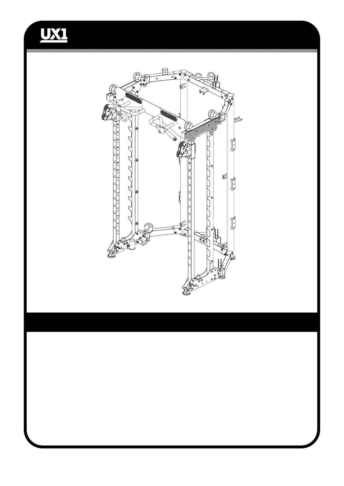
ASSEMBLY STEP 4
ASSEMBLY STEP 4 INSTRUCTIONS
- 12 -
1. Quick release lock foot (36) is installed on the main frame with M8*16 hexagon bolt (40),
Ø8 flat washer (41), Ø12*59.5 inner shaft (35).
2. Use M10*75 hexagon bolt (4), Ø10 flat washer (6), M10 lock nut (5) to fix guide rod
holder (34) to main frame.
3. Assemble the crown fixed plate right (38), crown fixed plate left (39) with M10*20
hexagon bolt (4), Ø10 flat washer (6), M10 lock nut (5) to main frame.
4. Front crown (37) is fixed with M10*20 hexagon bolt (13), Ø10 large flat washer (14),
Ø20*85 inner shaft (12) is installed on the crown fixed plate right (38) and fixed to crown
fixed plate left (39) with Ø12*110 crown release pin (42).
5. Use M10*70 hexagon bolt (26), flat washer (6), M10 locking nut (5), large flat washer
(14) to fix smith machine racking plate (33) to main frame.