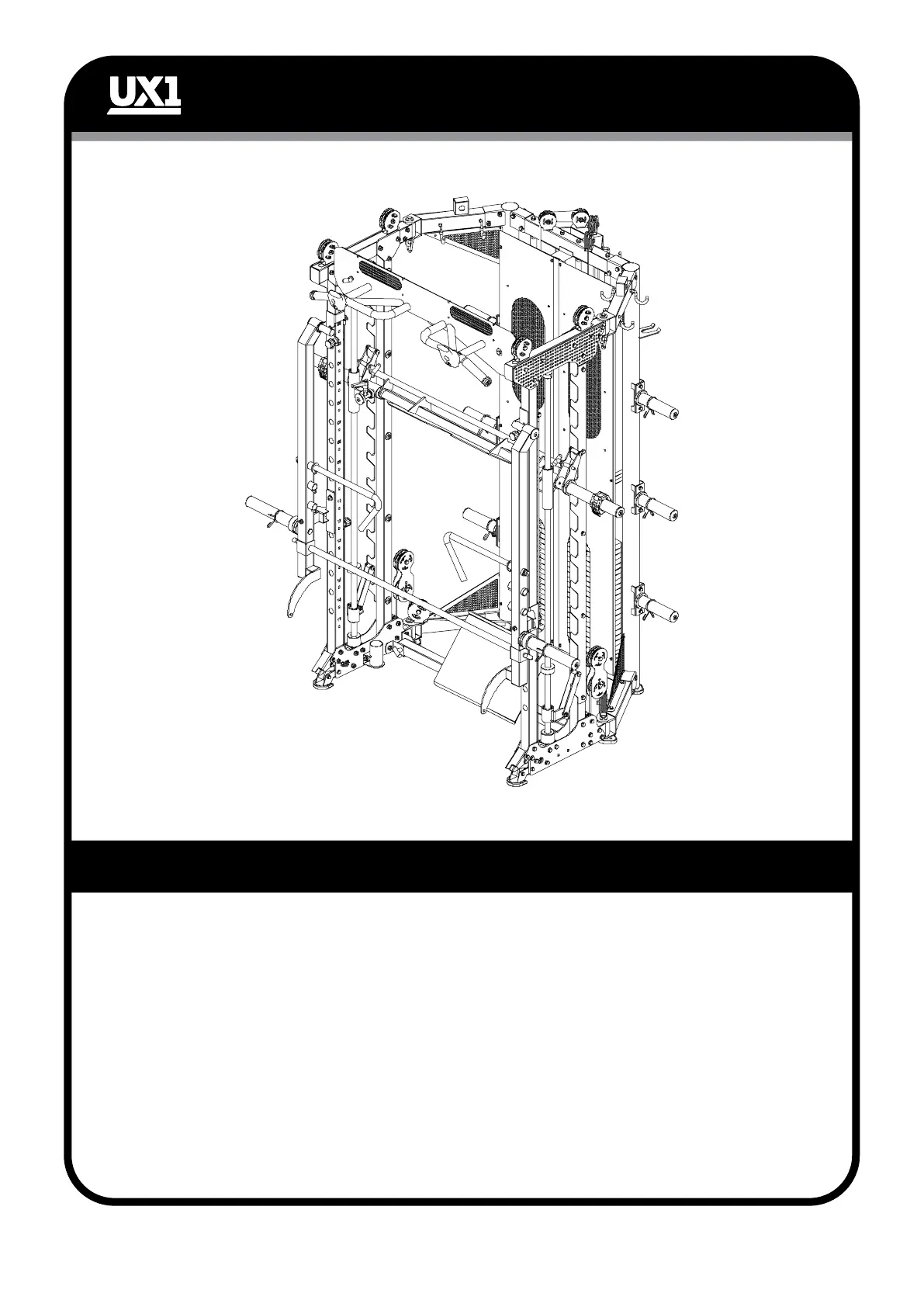
ASSEMBLY STEP 11
ASSEMBLY STEP 11 INSTRUCTIONS
- 26 -
1. Connects the jammer arm fixing bracket left (108) and jammer arm left (109) with
M10*20 hexagon bolt (67), Ø10 spring washer (68) and Ø50*Ø19*Ø11 aluminium cover
(61).
2. Connects the jammer arm fixing bracket right (103) and jammer arm right (104) with
M10*20 hexagon bolt (67), Ø10 spring washer (68) and Ø50*Ø19*Ø11 aluminium cover
(61).
3. The jammer arm stopper bracket left and right (120) (106), hang on the front stainless
steel posts when using the jammer arms.
4. The jammer arm handle (105) is installed on the left and right jammer arms (104) (109).
5. Use Ø10*85 T-shape pin (101) to install the jammer arm front rod (107) to both jammer
arms.


 To Next Page