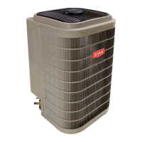
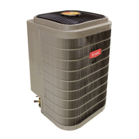
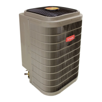
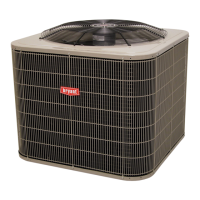
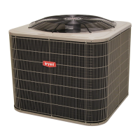
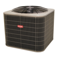
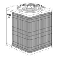
288BNV EVOLUTION
R
V VARIABLE SPEED HEAT PUM P
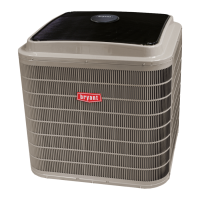
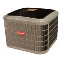
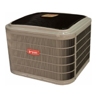
189BNV EVOLUTION
R
V VARIABLE SPEED AIR CONDITIONER
WITH PURONr REFRIGERANT
Service Manual
TABLE OF CONTENTS
PAGE
UNIT IDENTIFICATION 2.................................................................................
REFRIGERANT PIPING LENGTH LIMITATIONS 3...........................................................
LONG LINE APPLICATIONS 3.............................................................................
SAFETY CONSIDERATIONS 4.............................................................................
GENERAL INFORMATION 4..............................................................................
ELECTRICAL 5..........................................................................................
MAJOR COMPONENTS 5--7...............................................................................
AOC Bo ard 5..........................................................................................
Inverter 5..............................................................................................
Variable Speed Compressor 5..............................................................................
Electronic Expansion Valve (EXP) 6.........................................................................
Outdoor Fan Motor 6.....................................................................................
Pressure Transducer (SPT) 6...............................................................................
Pressure Equalizer Valve (PEV) 6...........................................................................
Outdoor Coil Thermistor (OCT) 6...........................................................................
Suction Thermistor (OST) 7...............................................................................
Discharge Thermistor (ODT) 7.............................................................................
Crankcase Heater 7......................................................................................
Time--Delays 7.........................................................................................
COMMUNICATION AND STATUS FUNCTION LIGHTS 7.....................................................
CHECK CHARGE 9.......................................................................................
TROUBLESHOOTING 9--13................................................................................
Service Tool 14-- 31......................................................................................
System Communication Failure 14..........................................................................
Model Plug 14..........................................................................................
Status Codes 14.........................................................................................
Variable Speed Compressor Winding Resistance 14.............................................................
Fan Motor 15...........................................................................................
Control Fault 15........................................................................................
Brown Out Protection 15..................................................................................
230v Line (Power Disconnect) Detection 15...................................................................
Pressure Switch Protection 15..............................................................................
Suction Pressure Transducer (SPT) 15........................................................................
Temperature Thermistors 16...............................................................................
Fault Code Action Table 18................................................................................
Variable Speed Drive LED Location and Description 25..........................................................
Compressor Power Harness Assembly Replacement 26..........................................................
Inverter Assembly with Shield Gasket Installation 28............................................................
Compressor Replacement 31...............................................................................
WIRING DIAGRAMS 34-- 35.................................................................................
REFRIGERATION SYSTEM 36-- 40..........................................................................
Refrigerant 36..........................................................................................
Compressor Oil 36.......................................................................................
Servicing Systems on Roofs With Synthetic Materials 36.........................................................
Brazing 36.............................................................................................
Service Valves and Pump down 36..........................................................................
Liquid Line Filter Drier 39................................................................................
Suction Line Filter Drier 39................................................................................
Thermostatic Expansion Valve (TXV) 39.....................................................................
Accumulator 40.........................................................................................
REFRIGERATION SYSTEM REPAIR 40.....................................................................

 Loading...