23
5. Check and inspect heating section before each heating
season. Clean and adjust when necessary.
6. Check flue hood and remove any obstructions, if
necessary.
AIR FIL
TER
NOTE: Never operate the unit without a suitable air filter in the
return--air duct system. Always replace the filter with the same
dimensional size and type as originally installed. (See Table 1 for
recommended filter sizes.)
Inspect air filter(s) at least once each month and replace
(throwaway--type) or clean (cleanable--type) at least twice during
each heating and cooling season or whenever the filter(s)
becomes clogged with dust and/or lint.
EVAPORATOR BLOWER AND MOTOR
NOTE: All motors are prelubricated. Do not attempt to lubricate
these motors.
For longer life, operating economy, and continuing efficiency,
clean accumulated dirt and grease from the blower wheel and
motor annually.
CLEANING THE BLOWER MOTOR AND WHEEL
1. Remove and disassemble blower assembly as follows:
a. Remove unit access panel.
b. Disconnect motor lead from blower relay (BR).
Disconnect yellow lead from terminal L2 of the
contactor.
c. On all units, remove blower assembly from unit.
Remove screws securing blower to blower partition
and slide assembly out. Be careful not to tear
insulation in blower compartment.
d. Ensure proper reassembly by marking blower wheel
and motor in relation to blower housing before
disassembly.
e. Loosen setscrew(s) that secures wheel to motor shaft.
Remove screws that secure motor mount brackets to
housing, and slide motor and motor mount out of
housing.
2. Remove and clean blower wheel as follows:
a. Ensure proper reassembly by marking wheel
orientation.
b. Lift wheel from housing. When handling and/or
cleaning blower wheel, be sure not to disturb balance
weights (clips) on blower wheel vanes.
c. Remove caked--on dirt from wheel and housing with a
brush. Remove lint and/or dirt accumulations from
wheel and housing with vacuum cleaner, using soft
brush attachment. Remove grease and oil with mild
solvent.
d. Reassemble wheel into housing.
e. Reassemble motor into housing. Be sure setscrews are
tightened on motor shaft flats and not on round part of
shaft.
f. Reinstall unit access panel.
3. Restore electrical power to unit. Start unit and check for
proper blower rotation and motor speeds during heating
and cooling cycles.
FLUE GAS PASSAGEWAYS
To inspect the flue collector box and upper areas of the heat
exchanger:
1. Remove the combustion blower wheel and motor
assembly according to directions in the Combustion--Air
Blower section.
2. Remove the 3 screws holding the blower housing to the
flue collector box cover (See Fig. 23).
3. Remove the 12 screws holding the flue collector box
cover (See Fig. 24) to the heat exchanger assembly.
Inspect the heat exchangers.
4. Clean all surfaces, as required, using a wire brush.
COMBUSTION--AIR BLOWER
Clean periodically to assure proper airflow and heating efficiency.
Inspect blower wheel every fall and periodically during the
heating season. For the first heating season, inspect blower wheel
bimonthly to determine proper cleaning frequency. To inspect
blower wheel, remove draft hood assembly. Shine a flashlight
into opening to inspect wheel. If cleaning is required, remove
motor and wheel as follows:
1. Remove unit access panel (See Fig. 22).
2. Remove the 7 screws that attach induced--draft motor
mounting plate to blower housing (See Fig. 23).
3. Slide the motor and blower wheel assembly out of the
blower housing (See Fig. 23). Clean the blower wheel. If
additional cleaning is required, continue with Steps 4 and
5.
4. To remove blower, remove 2 setscrews (See Fig. 23).
5. To remove motor and cooling fan assembly, remove 4
screws that hold blower housing to mounting plate.
6. To reinstall, reverse the procedure outlined above.
LIMIT
SWITCH
Remove unit access panel. Limit switch is located on the blower
partition.
BURNER
IGNITION
Unit is equipped with a direct spark ignition 100 percent lockout
system. Ignition module is located in the control box. Module
contains a self--diagnostic LED. During servicing, refer to label
diagram for LED interpretation.
If lockout occurs, unit may be reset by either momentarily
interrupting power supply to unit or by turning selector switch to
OFF position at the thermostat.
MAIN
BURNERS
At the beginning of each heating season, inspect for deterioration
or blockage due to corrosion or other causes. Observe the main
burner flames and adjust, if necessary.
UNIT DAMAGE HAZARD
Failure to follow this caution may result in reduced unit and/or
component life.
Do No t redrill an orifice. Improper drilling (burrs,
out--of--round holes, etc.) can cause excessive burner noise
and misdirection of burner flame. Replace with correct sized
orifices.
!
CAUTION
REMOVAL OF GAS TRAIN
To remove the gas train for servicing:
1. Shut off main gas valve.
2. Shut off power to unit.
3. Remove unit access panel (See Fig. 22).
4. Disconnect gas piping at unit gas valve.
5. Remove wires connected to gas valve. Mark each wire.
6. Remove ignitor and sensor wires at the ignitor module.
7. Remove the mounting screw that attaches the burner rack
to the unit base (See Fig. 24).
8. Slide the burner rack out of the unit (See Fig. 21 and 24).
9. To reinstall, reverse the procedure outlined above.
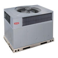
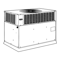
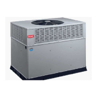
574B
 Loading...