even though its instructions say to do so. The necessary interlock-
ing to keep both the heat pump and furnace from operating at the
same time is done by Zone Perfect Plus.
The special 3-stage auxiliary heat feature of Bryant thermostats is
incorporated into Zone Perfect Plus. This requires an FK type fan
coil and specific heater packages with a single-speed heat pump.
See FK fan coil Installation Instructions.
IX. UNDERSTANDING SEQUENCE OF OPERATION
A. Temperature Set Points
The Zone Perfect Plus System uses 2 temperature set points for
each zone, the higher for cooling and the lower for heating. A
minimum difference of 2°F is enforced between the 2 set points.
Each set point may be manually adjusted or controlled by a
programmed time schedule established by the home or business
owner.
B. Heating and Cooling Comfort Set Points
If space temperature is between heating and cooling set points for
the zone, then the zone is said to be "satisfied" with respect to
temperatures. When a zone is satisfied, no heating or cooling is
required. When all zones are satisfied, there is no demand and the
equipment is turned off. For example, if cooling set point is 76°F
and heating set point is 72°F, then a space temperature of 73°F is
assumed to be satisfactory and no heating or cooling of the zone is
required.
If space temperature in a zone falls below heating set point, then
that zone needs to have heat added to zone which will raise space
temperature back to heating set point. For example, if heating set
point is 72°F and space temperature is 70°F, then space tempera-
ture must be raised 2°F in order for zone to be satisfied. In this
case, temperature "heating demand" for zone is 2°F. (72° minus
70°F.)
Otherwise, if space temperature in a zone rises above cooling set
point, then that zone needs to have heat removed from zone which
will lower space temperature back to cooling set point. For
example, if cooling set point is 76°F and space temperature is
77°F, space temperature must be lowered 1°F in order for zone to
be satisfied. In this case, "cooling demand" for zone is 1°F. (77°
minus 76°F.)
C. Out Feature
A new feature called OUT can be selected via the OUT button.
When this selection is made, the system is being told that the
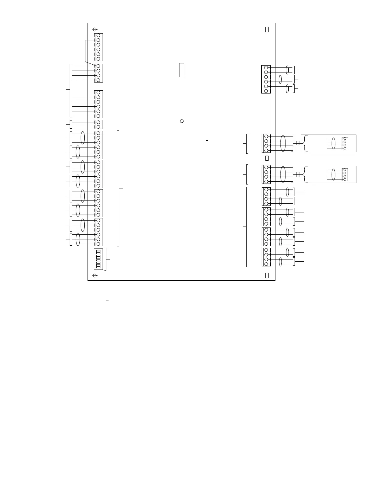
→ Fig. 11—8-Zone System Wiring Diagram
A98087
O REVERSING VALVE COOL
B REVERSING VALVE HEAT
RH HEATING TRANSFORMER
DHUM DEHUMIDIFY
DEF DEFROST
RC COOLING TRANSFORMER
SEE
FIGURES FOR
EQUIPMENT
WIRING
24 VAC ZONING
TRANSFORMER
C
RZ
8 ZONE EQUIPMENT CONTROLLER
HUM HUMIDIFY
G FAN
W2 HEAT STAGE 2
W1 HEAT STAGE 1
Y2 COMPRESSOR STAGE 2
Y1 COMPRESSOR STAGE 1
CLS7
COM7
OPN7
CLS8
HPTC
LAT
LATC
HPT
OAT
OATC
DAMPERS
8
1
CLS_
COM_
OPN_
=
=
=
CLOSE
COMMON = 24VAC FROM RZ
OPEN
COM8
OPN8
ZONE 7
DAMPER
ZONE 8
DAMPER
OUTDOOR AIR
TEMP SENSOR
LEAVING AIR
TEMP SENSOR
HEAT PUMP
TEMP SENSOR
CLS5
COM5
OPN5
CLS6
COM6
OPN6
ZONE 5
DAMPER
ZONE 6
DAMPER
CLS3
COM3
OPN3
CLS4
COM4
OPN4
ZONE 3
DAMPER
ZONE 4
DAMPER
CLS1
COM1
OPN1
CLS2
COM2
OPN2
ZONE 1
DAMPER
ZONE 2
DAMPER
JUMPER NEEDED
FOR HEAT PUMP
APPLICATIONS
DAMPER
FUSE
3A
OPTION
SWITCHES
NOTE SWITCH
#8 IS AT TOP
D20
(LED)
DEFROST
NOTES:
* = OPTIONAL COMPONENTS
= INSTALLING ZONE 1 REMOTE SENSOR AT OS1 AND OS1C WILL OVERRIDE
TEMPERATURE SENSOR ON USER INTERFACE
= COMMUNICATION BUS ARE IN PARALLEL WITH EACH OTHER
(EITHER CONNECTOR CAN BE USED)
†
†
V+
RS+
RS-
VG
REMOTE
SENSORS
COMMUNICATION
BUS
ZONE 3
SENSOR
ZONE 4
SENSOR
OPTIONAL
ZONE 1
SENSOR
ZONE 2
SENSOR
V+
COMMUNICATION
BUS
RS+
RS-
VG
OS1
OS1C
ZS2
ZS2C
ZS3
ZS3C
ZS4
ZS4C
ZONE 7
SENSOR
ZONE 8
SENSOR
ZONE 5
SENSOR
ZONE 6
SENSOR
ZS5
ZS5C
ZS6
ZS6C
ZS7
ZS7C
ZS8
ZS8C
V+
USER INTERFACE
RS+
RS-
VG
VG
V+
SMART SENSORS*
RS+
RS-
WHITE
RED
BLUE/YELLOW
GREEN
WHITE
RED
BLUE/YELLOW
GREEN
†
†
†
—7—
→