12
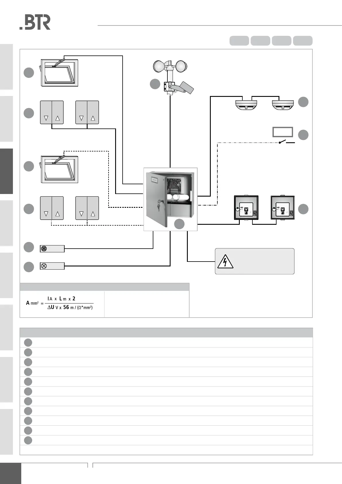
RWA - Control Unit BCR
Formula to calculate the required wire cross-section of a infeed line
A = cross-section of the wire in mm
2
L = line length in m
I = current of connected drives in A
∆U = line voltage drop = 2 V DC
PreParing assembly
Legend
1
Output for drive line 1, 24 V DC for smoke and heat exhausting and natural ventilation
2
Input for ventilation line 1 (max. 10 vent buttons)
3
Output for drive line 2 (only available for BCR 8 A and BCR 12 A)
4
Input for ventilation line 2 (max. 10 vent buttons) (only available for BCR 8 A and BCR 12 A)
5
Housing of control unit
6
Connections for wind and rain sensor (disabled in case of alarm and power loss)
7
Input for smoke detectors (max. 10)
8
Input for signal from external re alarm system (alternative connection) to smoke detectors
9
Input for break-glass units (HSE – max. 10)
10
Output for signal transduction 1 (alarm release)
11
Output for signal transduction 2 (collective fault)
----- only available for BCR 8 A and BCR 12 A
RAUCHABZUG
O K
!
RAUCHABZUG
O K
!
BMA
1
2
4
3
11
10
6
9
8
7
Operating voltage, primary
195 ... 253 V AC
Route via external fuse and
switching component!
INFO
INFO
(see formula)
Cable: 5 x 1,5 or 7 x 1,5 mm
2
Length: max. 200 m
Cable: 2 x 2 x 0,8 mm
2
Length: max. 400 m
Cable: 2 x 2 x 0,8 mm
2
Length: max. 400 m
Cable: 4 x 2 x 0,8 mm
2
Length: max. 400 m
Cable: 4 x 2 x 0,8 mm
2
Length: max. 400 m
Cable: 2 x 2 x 0,8 mm
2
Length: max. 400 m
Cable: 2 x 2 x 0,8 mm
2
Length: max. 400 m
min. 3 x A
(see formula)
5
12 A8 A4 A2 A
03
connection facilities / cabling