15
RWA - Control Unit BCR
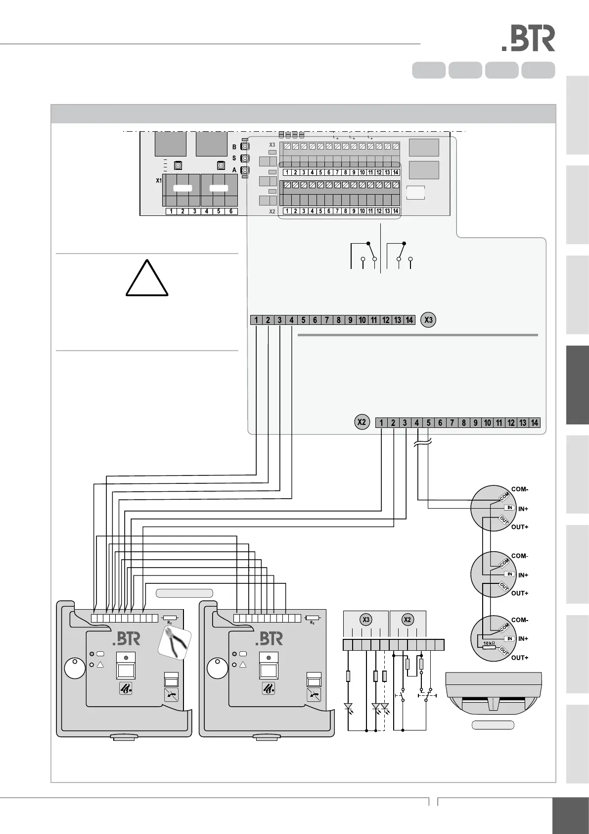
instAllAtion step 2:
C
onneCting smoke DeteCtors anD breakglass units
Connection of automatic and manual smoke detectors / BMZ
12 A8 A4 A2 A
red: open
green: close
Drive 1 Drive 2
GND
alarm
operation
fault
GND
GND
OPEN
CLOSE
REL 6 -
REL 6 -
REL 6 -
REL 7 -
REL 7 -
REL 7 -
com
n.c.
n.o.
com
n.c.
n.o.
button L2 -
button L2 -
LED -
LED -
LED -
GND
alarm
reset
GND
smoke detector
GND
GND
+24 V
GND
rain
GND
wind
OPEN
CLOSE
button L1 -
button L1 -
HSE -
HSE -
Alarm
Fault
(inverted)
+
smoke detector
OK
!
1 2 3 4 5 6 7 8 9 1110
OK
!
1 2 3 4 5 6 7 8 9 1110
R
E
1 2312 3 4
1 2 3 4 5 6 7 8 9 10 11
HSE - Break-glass unit
instAllAtion step 2:
connection: automatic and manual smoke detectors
04
The re detector connection is closed-circuit moni-
tored for line failures. Therefore, both the last smoke
detector and the last breakglass unit in the line must
be provided with a 10 kΩ resistor (RE).