18
RWA - Control Unit BCR
instAllAtion step 4:
C
onneCting PoWer suPPly
12 A8 A
instAllAtion step 4:
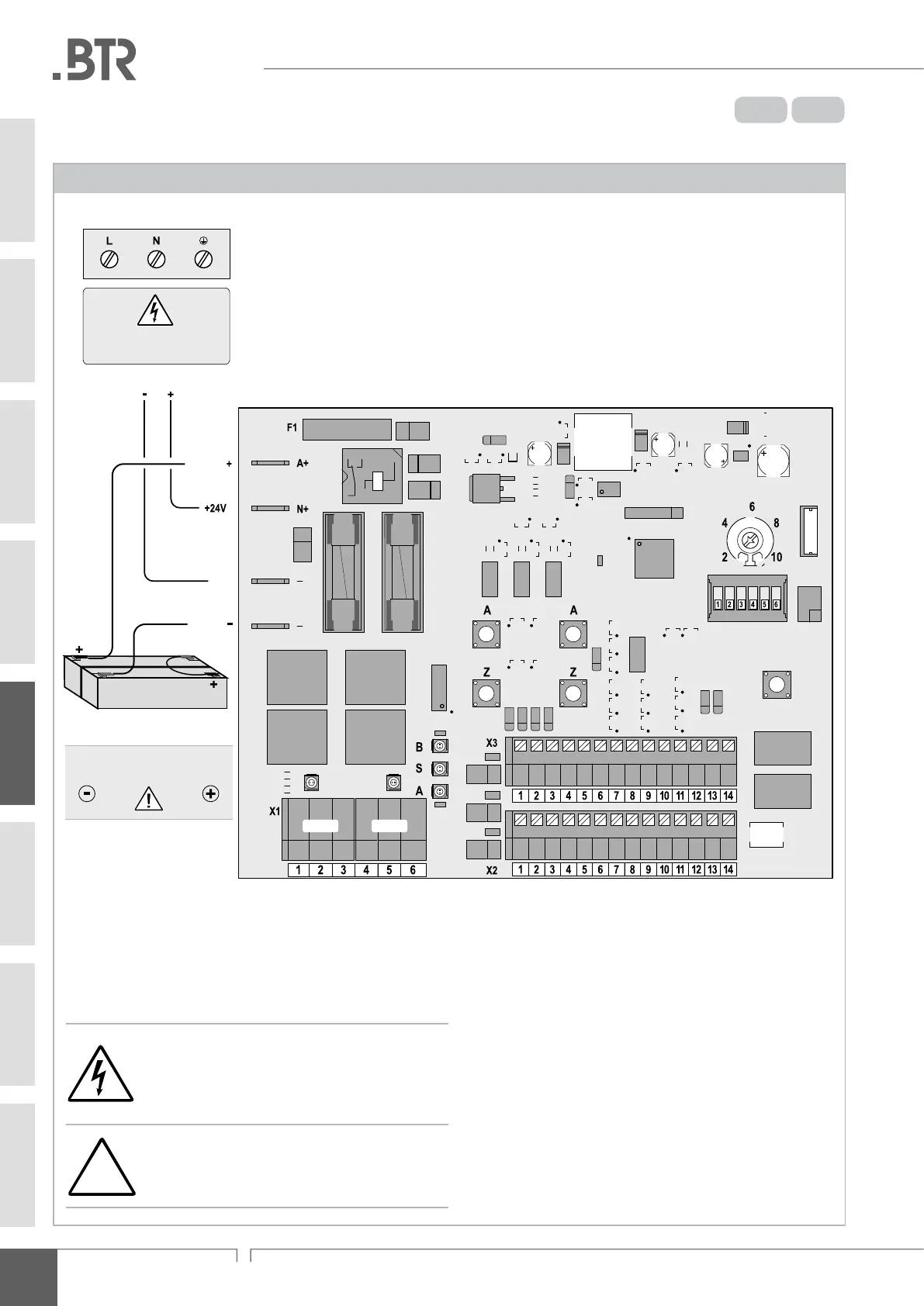
BCR 8 A und BCR 12 A connecting: poWer supply
Connection of power supply
reset
wind
T / SH
ML - A
HSE - A
RM - A
NF - A
BF - A
Battery
GND
Battery
F2 F3
Power Supply 24V
2 x back-up battery 7 Ah, 12V
L1
open
L2
open
L1
close
L2
close
red: open
green: close
Wind-Speed (reshold)
[m/s]
Drive 1 Drive 2
Ensure correct polarity
when connecting!
blue red
Operating voltage, primary
195 ... 253 V AC
-
-
Route line voltage supply via external fuse and
switching component. Only connect supply voltage
and accumulator set when disconnected from the mains
power supply! Switch off power supply and secure
against reconnection!
It is essential to ensure correct polarity when connecting
the accumulator set! Incorrectly connected accu-
mulators will cause damage to the controller!
05