Mounting Instructions 2
5
• Remove the front panel of the boiler.
• Only necessary with the G124X, G224E, G234X and G334X
boilers.
• Remove the two screws and housing from the top of the
Ecomatic.
• Insert the two front feet of the control into the holes provided
on the top of the boiler.Then, firmly push down on the rear of
the control until it snaps into place.
• The sensor bundle consists of one thermistor (FK), two
capillaries and a spacer. Mount the sensors per the following
boiler specific instructions. The chrome well is supplied with
the Ecomatic.
G115, G205, G305: Replace brass well with chrome Ecomatic well.
The sensor bundle must be fully inserted into the Ecomatic well.
G124X: Unwrap the sensor bundle. Remove spacers from the chrome
well on the boiler. Remove the copper sleeve from one of the capilaries.
Install all 3 probes in with the Honeywell capillary.
G224E/G234X/G334X: The tridicator assembly should be moved to
the supply piping and replaced with the chrome plated Ecomatic we l l .
The sensor bundle must be inserted into this well.
• Fasten the control to the boiler jacket using the two screws as
shown.
1 Introduction
4
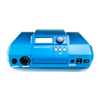
Case 2: Multiple zones with the main zone on
constant circulation
The heating curve is set in a similar way as in Case 1. A
room sensor is required in the constant circulation zone to
provide room temperature compensation for fine-tuning of
the heating curve. The main zone sets the water temperature
available to all secondary zones. Specified day and night
temperatures on the room sensor are used internally to
compute a heating curve during night mode.
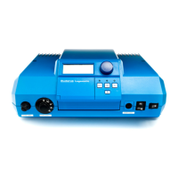
Case 3 : Multiple Temperatures
The heating curve for the high temperature zone(s)
is set on CIRCUIT 1. CIRCUIT 2 defines the low
temperature heating curve using a motorized mixing valve.
The HS2105 control positions the mixing valve based
on the outside and supply temperature measured by a strap-on
sensor. Each heating circuit can be equipped with an optional
room sensor.
Fig. 2: HS2105 heating curve with room sensor adjustment
Fig.3: High and low temperature heating curves; requires module FM241
MAX TEMP1
Heating Curve
(day mode)
Heating Curve
(night mode)
Burner
Differential
Pump Logic
Offset
200
180
160
140
120
100
80
60
Ref Temp
70 60 50 40 30 20 14 10 0 -10 -20 -30
OUTSIDETEMPERATURE (˚F)
Room Sensor
Compensation Effect
Room Sensor
Compensation Effect
MAX TEMP1
Heating Curve Circuit 2
(day mode)
Heating Curve Circuit 2
(night mode)
Heating Curve Circuit 1
(night mode)
Heating Curve Circuit 1
(day mode)
Burner
Differential
Pump Logic
Max Temp2
Offset
200
180
160
140
120
100
80
60
Ref Temp
Ref Temp
70 60 50 40 30 20 14 10 0 -10 -20 -30
OUTSIDETEMPERATURE (˚F)
 Loading...