EasyManua.ls Logo

Buderus Ecomatic HS 2105 - User Manual

Buderus Ecomatic HS 2105
20 pages
Print Icon
To Next Page IconTo Next Page
Loading...
Service Manual
Ecomatic HS 2105
Save These Instructions !
5647 488 5/98 USA
Question and Answer IconNeed help?

Do you have a question about the Buderus Ecomatic HS 2105 and is the answer not in the manual?

Summary

Introduction to Buderus HS2105

HS2105 Control Operation Overview

Overview of HS2105 functions, DHW, recirculation, night setback, and optional modules.

Case 1: On;Off Thermostat Heating Zones

Explains heating curve, REF TEMP, OFFSET, DAY/NIGHT TEMP, MAX TEMP 1, and PUMPLOGIC.

Case 2: Multi-Zone with Room Sensor

Describes heating curve adjustment with a room sensor for multi-zone systems.

Case 3: Multiple Temperature Zones

Explains setting heating curves for high and low temperature zones using a mixing valve.

Mounting Instructions for HS2105

Boiler Unit and Sensor Bundle Mounting

Step-by-step guide for mounting the control unit and installing sensor bundles for various boiler models.

Electrical Connections and Final Assembly Steps

Covers wire routing, strain reliefs, display adjustment, and final housing replacement.

Testing the Manual Reset High Limit (STB)

STB Testing Procedure and Safety Checks

Detailed steps for testing the manual reset high limit (STB) functionality.

Returning to Normal Operation Mode

Instructions to press the AUT button to return to normal operation after testing.

HS2105 Key Code Access and Configuration

Installation Level Access Procedure

Step-by-step guide to enter the installation level using the ENTER button and a pointed object.

Language Selection and Display Return

Instructions on changing the display language and exiting the installation mode.

HS2105 Program Overview and Navigation

Navigating Main Menus and Submenus

Describes how to access, navigate, and change values within the main menus and submenus.

Optional Module Compatibility

Lists optional modules (FM241, FM242, KM271) and their functions.

Installation Level Parameter List

A comprehensive list of all adjustable parameters in the installation level, their display names, and corresponding page numbers.

Installation Entries: Freeze Protection

Freeze Protection Setting (FREEZTEMP)

Configures automatic circulator operation for freeze protection based on outside temperature.

Changing FREEZTEMP Setting

Step-by-step guide to modify the freeze protection temperature setting.

Navigation and Display Return

Explains how to return to the main menu or standard display.

Installation Entries: Building Type

Building Type Setting (BLDG RESP)

Defines building insulation and heat storage capacity to optimize temperature response.

Changing BLDG RESP Setting

Procedure to modify the building type setting for optimal system response.

Installation Entries: Burner Type

Burner Installation Type (BURNER)

Selects the burner type (one-stage, two-stage, modulating) when module FM242 is installed.

Changing BURNER Setting

Steps to configure the burner installation type from the installation level.

Installation Entries: Modulating Burner

Minimum Firing Rate (MIN MOD)

Sets the minimum modulation percentage for a modulating burner.

Changing MIN MOD Setting

Procedure to adjust the minimum firing rate for modulating burners.

Installation Entries: Modulating Burner Time

Modulating Valve Time (MOD TIME)

Specifies the total time in seconds for a modulating burner to reach its full operating range.

Changing MOD TIME Setting

Steps to set the modulating valve operating time.

Installation Entries: Condensate Protection

Condensate Protection (PUMPLOGIC)

Configures the circulator interrupt temperature for condensate protection.

Changing PUMPLOGIC Setting

Procedure to adjust the pump logic temperature setting for condensate protection.

Installation Entries: Max Boiler Temp

Maximum Burner Shut-off Temp (MAX TEMP1)

Sets the maximum boiler temperature before the burner shuts off.

Changing MAX TEMP1 Setting

Steps to modify the maximum burner shut-off temperature.

Installation Entries: Flue Gas Temp

Flue Gas Temperature Sensing (FLUE TEMP)

Activates and sets a threshold for flue gas temperature monitoring with KM271 module.

Changing FLUE TEMP Setting

Procedure to set the flue gas temperature threshold for service messages.

Installation Entries: Heating Circuits

Heating System Layout Configuration

Defines the type of heating circuits (perimeter, floor) for proper curve setting.

Circuit 1 and Circuit 2 Options

Specifies configuration options for Circuit 1 and Circuit 2, including 'NO SYSTEM'.

Installation Entries: Heating Curves

Setting Reference Temperature (REF TEMP)

Selects the reference temperature at 14°F outside to establish the heating curve.

Heating Curve Adjustments

Explains how to fine-tune the heating curve based on room temperature performance.

Overview

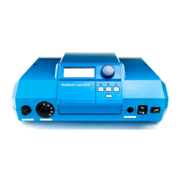
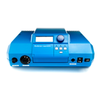
The Buderus Ecomatic HS 2105 is a hydronic heating system controller designed to manage various aspects of a heating system, including space heating, domestic hot water (DHW) production, and recirculation. It utilizes outdoor reset control based on an outdoor sensor to optimize heating efficiency. The system supports programmable night setback for customized operation and can be expanded with optional modules for 2-stage or dual burner control and motorized mixing valve control for floor heating applications.

Function Description:

The HS2105 integrates several key functions:

  • Space Heating: Operates on an outdoor reset heating curve, which adjusts boiler water temperature based on the outdoor temperature. The slope of this curve is set by the "REF TEMP" value, and the curve can be shifted up or down using the "OFFSET" setting. The control also computes a lower heating curve for night mode operation based on "DAY TEMP" and "NIGHT TEMP" values.
  • Domestic Hot Water (DHW) Heating: Provides priority DHW heating for indirect fired water heaters. During a call for DHW, the control can fire the burner up to the "MAX TEMP 1" setting for maximum recovery.
  • DHW Recirculation Pump: Supports periodic operation of a DHW recirculation pump.
  • Condensation Protection ("PUMPLOGIC"): Temporarily interrupts pump operation when the burner is running and boiler water temperature drops below a specified "PUMPLOGIC" setting to prevent condensation.
  • Freeze Protection ("FREEZTEMP"): Automatically permits heating circulators to run continuously in night mode if the outdoor temperature drops below the "FREEZTEMP" value, irrespective of the selected setback mode.
  • Building Response ("BLDG RESP"): Allows specification of the building's insulation and heat-storing capacity to enable the control to respond in a delayed fashion to outdoor temperature changes, maintaining comfortable indoor temperatures.
  • Burner Control: Can be configured for 1-stage, 2-stage, or modulating burner operation, depending on the installed FM242 module. For modulating burners, "MIN MOD" sets the minimum firing rate, and "MOD TIME" specifies the operating time for the modulating valve to go through its full range.
  • Heating Circuit Control: Designed for individual control of two heating circuits with different water temperatures. Circuit 1 typically handles perimeter heating (baseboard, radiators), while Circuit 2, if the FM241 mixing module is installed, can manage low-temperature heating like radiant floor heating. Each circuit's nature ("PERIM-HTG," "FLOOR-HTG," "NO SYSTEM") must be specified to the control to set the proper heating curve curvature.
  • Room Sensor Integration: For constant circulation zones, a room sensor can provide room temperature compensation for fine-tuning the heating curve. Specified day and night temperatures on the room sensor are used to compute a heating curve during night mode. Each heating circuit can be equipped with an optional room sensor.

Important Technical Specifications:

  • "REF TEMP" Range: Determines the slope of the heating curve. The desired water temperature for an outdoor temperature of 14°F is set as the "REF TEMP."
  • "FREEZTEMP" Range: 0°F to 50°F (Factory setting: 41°F).
  • "BLDG RESP" Settings: 1 (small heat storing capacity, medium insulation), 2 (medium heat storing capacity, high insulation - factory setting), 3 (high heat storing capacity, high insulation).
  • "MIN MOD" Range (Modulating Burner): 10% to 60% (Factory setting: 30%). Requires FM242 module.
  • "MOD TIME" Range (Modulating Burner): 5 seconds to 60 seconds (Factory setting: 12 seconds). Requires FM242 module.
  • "PUMPLOGIC" Range: 59°F to 140°F (Factory setting: 104°F for 1-stage burner). Specific values vary by boiler model (e.g., G315: 122°F for 1-stage, 131°F for 2-stage/modulating).
  • "MAX TEMP1" Range: 158°F to 210°F (Factory setting: 176°F). This is the maximum electronic high limit for boiler temperature.
  • "FLUE TEMP" Range: OFF/120-480°F (Factory setting: OFF). Requires KM271 module.
  • Modules:
    • FM241: Mixing valve control module, required for Circuit 2 (mixed zone) and modulating burner control.
    • FM242: Two-stage firing control module, required for 2-stage or modulating burner operation.
    • KM271: Communications module (currently not available in the U.S.A.), enables flue gas temperature sensing and ECOKOM communication.

Usage Features:

  • Key Code Access: Access to the installation level is protected by a special key code, ensuring that only heating contractors or trained operators can change critical settings.
  • Language Selection: The control supports language selection, with "DEUTSCH" (German) and "AMERICAN" available.
  • Dial and Button Interface: Navigation through menus and submenus, and adjustment of values, are performed using a dial and dedicated buttons (ENTER, RETURN, AUT).
  • Automatic Operation Resume: The control automatically returns to standard operation if no entries are made for 5 minutes.
  • Display Read-out: Provides clear display of current settings and parameters.
  • Sensor Bundle: Includes a thermistor (FK), two capillaries, and a spacer for mounting sensors according to boiler-specific instructions.
  • Emergency Override: The adjustable capillary high limit shuts off the burner in manual override mode, overriding the electronic "MAX TEMP1" setting.

Maintenance Features:

  • Manual Reset High Limit (STB) Testing: A procedure is outlined to test the manual reset high limit, involving running the burner until it shuts off at the aquastat setpoint, then bypassing the adjustable boiler aquastat to trip the STB at approximately 230°F. Resetting requires removing a safety nut and pressing a button.
  • Flue Gas Temperature Sensing (with KM271): When activated, the control can transmit a service message via an ECOKOM communication system if the flue gas temperature exceeds a preset value, indicating a need for boiler maintenance.
  • Relay Testing: The manual includes a section for testing relays on different system components.
  • LCD Test: A dedicated test for the LCD display.
  • Total System Reset: Allows resetting the general system to factory settings.
  • Version Number Display: Provides information on the control's software version.
  • Troubleshooting Procedures: A dedicated section for diagnosing and resolving issues.
  • Wiring Diagrams: Comprehensive diagrams (pages 40-46) for electrical connections.

Buderus Ecomatic HS 2105 Specifications

General IconGeneral
BrandBuderus
ModelEcomatic HS 2105
CategoryControl Systems
LanguageEnglish

Related product manuals