Read, Understand, Follow and Save These Instructions
Read, understand and follow all of these instructions and warnings (Instructions) before installing and using this product. Install and use this product only
as specified in these instructions. Improper installation or use of this product may result in property damage, serious injury, and/or death. Never allow
installation or use of this product by anyone without providing them with these instructions. You must read, understand and follow all instructions and
warnings for any product(s) to which this product is used in conjunction with or installed. Save these instructions with the product for use as a reference
for any future installation and use of the product.
Bulldog
®
Velocity Series
™
Jack
Failure to follow all warnings and instructions may result in product
failure, property damage, serious bodily injury, and/or death.
• This product must be installed and used in strict accordance with these
instructions. Purchaser/owner must not alter or modify the product.
• Operator and bystanders should never position any part of body under or
on the path of any portion of this product or the load being supported, or
moved.
• Do not allow children to play on or around this product or the load being
supported, or moved.
• Never exceed the maximum rated capacity. Refer to stamped markings
or decals to obtain rated capacity.
• Periodically check mounting hardware for proper torque and tighten if
necessary.
• Always replace bent, broken, or worn parts before using this product.
• To avoid accidental shock and/or damage to the electrical system,
disconnect the battery ground cable before installation.
• Secure the load, vehicle and trailer from rolling (by blocking wheels) when
operating jack or coupling trailer.
• These jacks are designed for vertical loading. Excessive side forces may
cause jack failure and must be avoided.
• Do not remove the tamper-resistant screws that secure the motor assembly
to the jack. Removal will cause sudden lowing of the trailer unless
properly supported.
1. PREPARE THE TRAILER
1.1 Support the trailer by connecting the coupler to the towing vehi-
cle or by the use of jack stands.
1.2 Chock the wheels of the trailer.
2. MOUNTING THE JACK
When considering the mount location of the jack, be certain to have
adequate ground clearance when fully retracted. Inade-
quate ground clearance may result in property damage.
2.1 Opon 1: The jack must be attached directly to the trailer
frame with a minimum of four (4) ½” grade 5 fasteners; one fastener
in each side of the two mounting plates on the jack (See Figure B).
Torque hardware to 50 ft-lbs.
Opon 2: The jack must be attached directly to the trailer
frame with a minimum of four (4) U-bolts utilizing a total of eight
holes on the mounting plates; two on the upper section and two on the
lower (See Figure C). Torque hardware to 50 ft-lbs.
2.2 On aluminum trailers, it is recommended to use isolation pads
between the contact points of the jack and trailer (including hardware)
to reduce galvanic corrosion.
3. BATTERY CONNECTION
3.1 Connect the battery leads directly to the trailer battery: red
lead to the positive terminal post of the battery, black lead to the nega-
tive terminal post of the battery. Vehicle wiring will not
provide adequate amperage for this product.
3.2 Secure the battery leads with cable-ties, wire loom, etc.
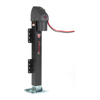
DO NOT
REMOVE SCREW!
A. Manual Override Port
B. Motor Assembly
C. Remote Control Connector Port
D. U-Bolt
E. Mounting Plate
B
C
D
E
A
Fig. A
Installation Instr uctions
COMPONENTS OF THE JACK:
(Figure A)
A. Remote Control
B. Wiring Pigtail
C. Toggle Switch
NOTE: Use silicone-based, dielectric grease on the
connection between the remote and power head.
COMPONENTS OF THE
REMOTE CONTROL: (Figure D)
Opon 2: Four (4) U-Bolts
Opon 1: Four (4) Bolts
Fig. B Fig. C
B.