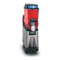
Do you have a question about the Bunn BUNN-O-MATIC ULTRA-1 and is the answer not in the manual?
| Model | ULTRA-1 |
|---|---|
| Manufacturer | Bunn |
| Material | Stainless Steel |
| Power Source | Electric |
| Voltage | 120V |
| Type | Coffee Dispenser |
Information on accessing internal components for service and repair.
Procedures for testing, removing, and replacing auger motors.
Steps for servicing and replacing auger motor capacitors.
Detailed instructions for the removal and replacement of the auger shaft assembly.
Testing, removal, and replacement procedures for the circuit breaker.
Service procedures for the Americold compressor on ULTRA-2 models.
Service procedures for the Embraco compressor on ULTRA-2 models.
Service procedures for appliance compressors on ULTRA-1 models.
Service procedures for Danfoss compressors on ULTRA-1B models.
Testing and replacement of relays or contactors on early models.
Procedures for testing and replacing the main control board.
Instructions for checking and adjusting the cooling drum alignment.
Procedures for testing, removing, and replacing the fan on ULTRA-2 units.
Procedures for testing, removing, and replacing the fan on ULTRA-1 units.
Testing and replacement of the hot gas temperature sensor.
Procedures for replacing the lamp cord assembly.
Steps for testing and replacing the lamp cord connector.
Instructions for servicing and replacing lamp holder/socket assemblies.
Testing and replacement procedures for the lamp relay.
Testing and replacement of the membrane switch on ULTRA-2 models.
Testing and replacement of the membrane switch on ULTRA-1 models.
Procedures for testing, removing, and replacing solenoids.
Testing and replacement of the temperature sensor.
Instructions for testing and replacing the torque sensor circuit board.
Procedures for testing and replacing the unit's transformer.
Diagram illustrating the coolant flow and component layout for ULTRA-1.
Diagram illustrating the coolant flow and component layout for ULTRA-2.
Map showing triac assignments and connections for the ULTRA-1 control board.
Map showing triac assignments and connections for the ULTRA-2 control board.
Detailed chart listing pin functions, wire colors, and voltage for ULTRA-1.
Electrical schematic illustrating wiring connections for the ULTRA-1 model.
Detailed chart listing pin functions, wire colors, and voltage for ULTRA-2.
Electrical schematic for ULTRA-2 AF models, showing component wiring.
Electrical schematic for ULTRA-2B AF models, showing component wiring.