Inha Works Ltd. 2009 14 (31)
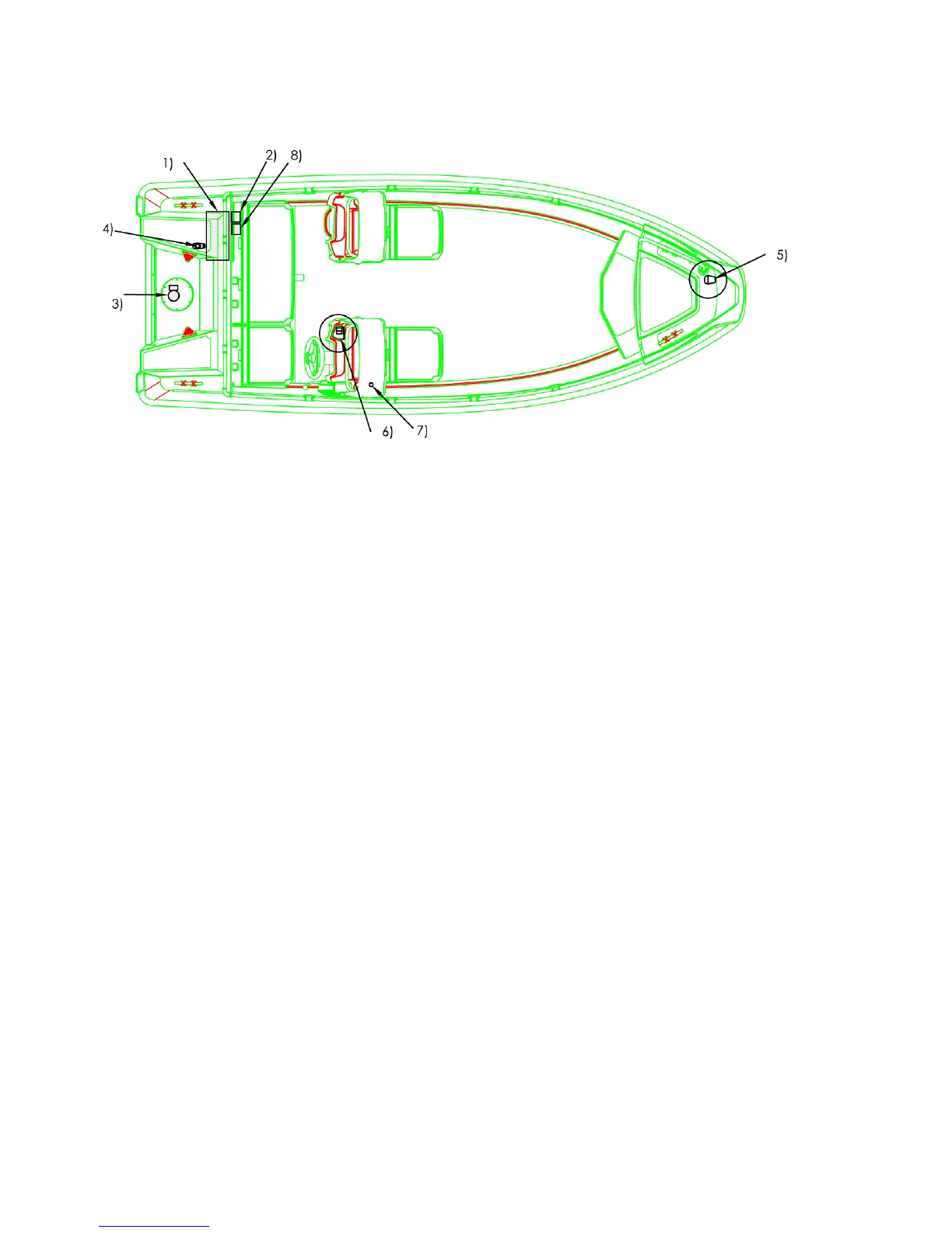
Diagram 4. Location of electrical devices:
1) Accumulator housing;
2) Main power switch;
3) Bilge pump;
4) Mast light (detachable), white 360°;
5) Navigation light (detachable), with colour sectors;
6) Switch panel (see Diagram 5.);
7) Power outlet, 12V DC, 10A;
8) Fuse box (see Diagram 6.)