Inha Works Ltd. 2009 15 (31)
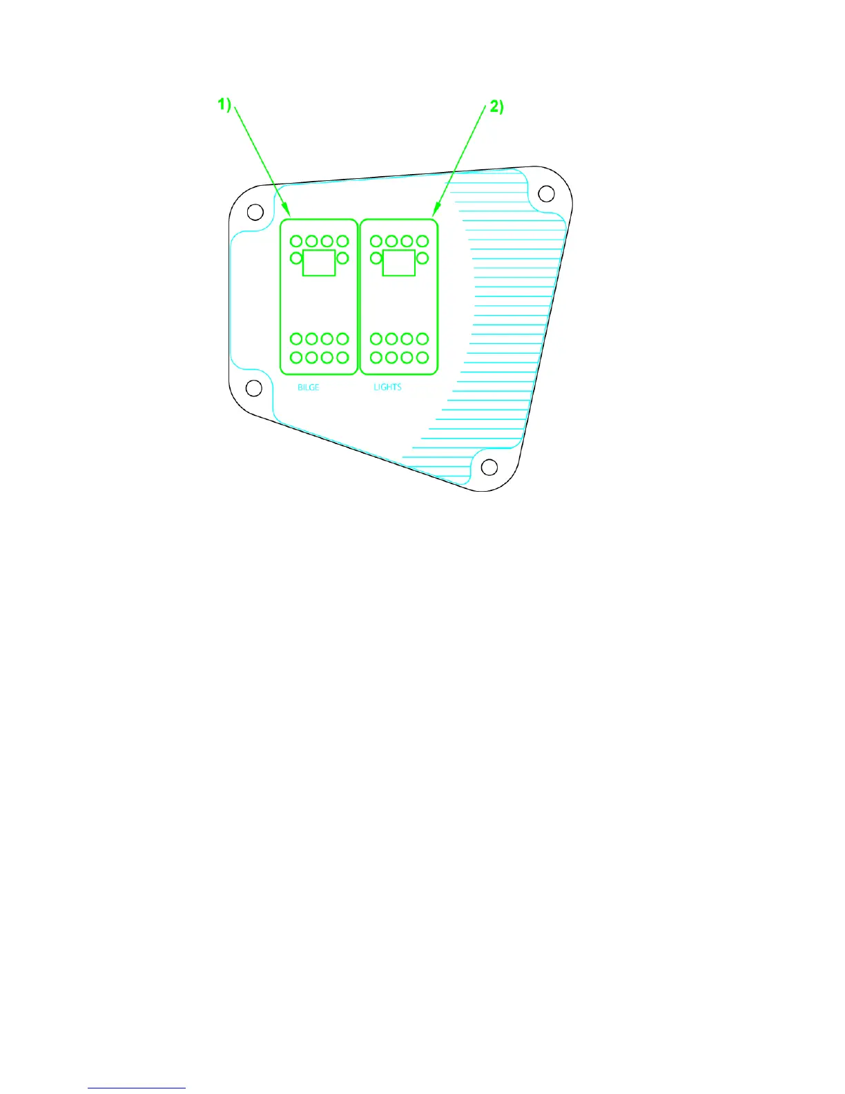
Diagram 5. Switch panel; 1. Operating switch for bilge pump; 2. Navigation light
switch
Circuit fuses are located next to the main switch in a separate fuse box inside the
rear seat on the left side of the boat. The Buster L uses automatic fuses which can
be reconnected after overloading by pushing the tripped pin back down. In the
electrical system, there are two extra circuits equipped with fuses (Extra 1 5A and
Extra 2 10A). Accessories installed post-production can be connected to these. The
leads for these circuits are behind the switch panel on the steering pulpit. Do not
replace normal fuses with fuses intended for a higher current feed. Similarly, do not
install as part of the electrical system components which exceed the nominal ampere
value of the respective circuit.