www.bvmsystems.co.uk
sales@bvmsystems.co.uk
40-0287-12
- 5 -
(see Figure 2). The polarity of these inputs must be respected by connecting the HCCT2 and
LCCT2 inputs to ground as shown. Use a schematic of the target CVT to identify the connec-
tion points for these MU inputs. In all cases a marked up CVT schematic must be used for the
design, installation and checking of the MU installation.
In many cases the bottom of the capacitor circuit is called the ‘HF’ terminal as this is where
power line equipment can be connected. The bottom of the EMU circuit is sometimes referred
to as P2 or N.
The MU is tted with a Phoenix UTA 89 TS35 DIN rail adapter and in many cases this can be
used to mount the MU on an available section of DIN rail in the CVT terminal box. The DIN rail
adapter can be removed and the three mounting holes can be used with a third party custom
bracket if required.
After the Measurement Unit has been installed the terminations of the HCCT and LCCT inputs
must be carefully checked to ensure that they have been correctly and securely made and are
physically robust, as an incorrect or faulty connection will result in LETHAL VOLTAGES being
present in the CVT secondary terminal box when the CVT is energised. If in any doubt about
the installation or connection points for the MU inputs consult a qualied technical expert in your
organisation.
The HCCT and LCCT input circuits are low impedance circuits with guaranteed continuity that
will not have any impact on the earth circuits of the Capacitor or EMU circuits of the CVT. These
circuits are formed using a single piece of cable with no connections or joints.
For the safe operation of the CVT it is essential that the integrity of capacitor and EMU earth
paths are preserved. To ensure this is the case we recommend carrying out the following test
after the MU has been installed in the CVT secondary terminal box.
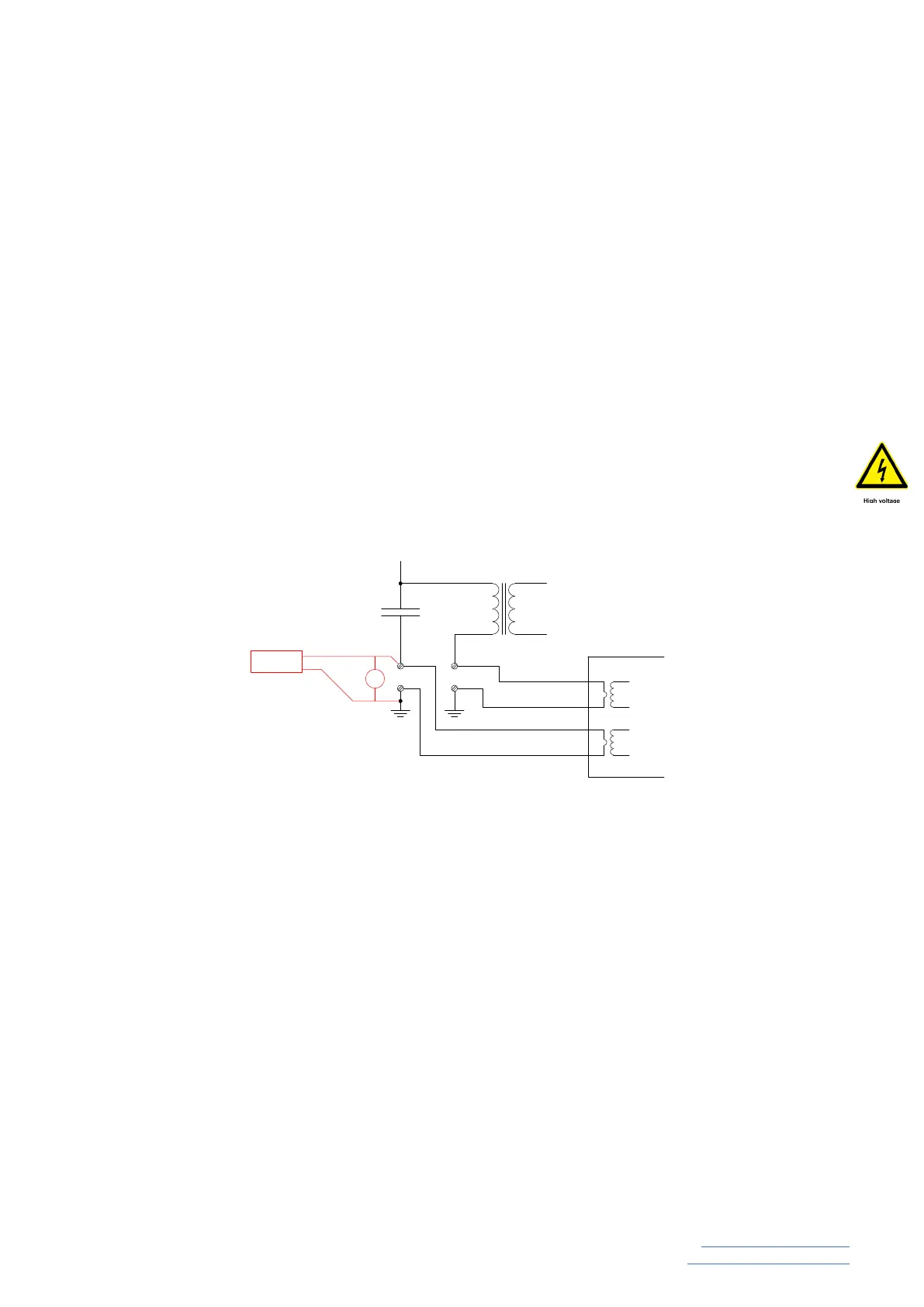
• Using a secondary injection test set (e.g. Sverker) inject 1A ac between the bottom of the
capacitor stack (HF) and ground.
• Measure the voltage drop from the bottom of the capacitor stack and ground (Figure 3)
• The measured voltage should be less than 40mV ac (equivalent to 40mΩ)
• Repeat the about test between the bottom of the EMU and ground where the measured volt-
age should be less than 60 mV.
C2
LCCT 1
LCCT 2
HCCT 1
HCCT 2
a
n
N / P2
HF
Sverker
V
Figure 3
 Loading...