www.bvmsystems.co.uk
sales@bvmsystems.co.uk
40-0287-12
- 4 -
Measurement Unit is also equipped with a test circuit that can be used for on-site testing and
calibration. Detailed dimensions of the Measurement Unit are given in Appendix I. It is equipped
with three M3 mounting holes on the base. These holes are compatible with the Phoenix UTA98
DIN rail adapter (provided) and can also be used together with other custom made mounting
plates.
1.2 The Interconnecting Cable
The Interconnecting Cable, with a standard length of 3 metres, takes the signals from the Meas-
urement Unit to the SCM. Lengths up to 5m are available on request. Both ends of this cable
are provided pre-terminated and equipped with the appropriate glands for making off in the CVT
secondary Terminal Box and the SCM Box. This steel wire armour (SWA) cable contains two
individually screened twisted pairs together with a collective screen. The twisted pair conduc-
tors in this cable are stranded with 0.5mm
2
nominal conductor area - usually a 16/0.2 conductor
stranding.
1.3 The SCM
The SCM is designed to be mounted on the structure of the CVT as shown in Figure 1. Dimen-
sions and mounting details for the box are provided in Appendix II. The OEM must provide a
mounting plate or bracket on the CVT structure compatible with the holes shown in the drawing
in Appendix II. The mounting plate is not supplied with the PQSensor™ as there many different
types of CVT support structures.
2 INSTALLATION OF THE MEASUREMENT UNIT IN THE CVT TERMINAL BOX
Whether the PQSensor is being installed in a new CVT at the time of factory test or being ret-
rotted to a CVT that is already in service the rst step is to install the MU in the secondary ter-
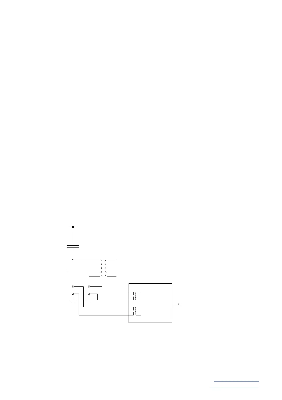
minal box of the CVT. The function of the MU is to measure the currents owing in the capacitor
divider circuit and in the primary winding of the CVT wound transformer (the electromagnetic
unit or EMU). These circuits are normally available in the CVT secondary terminal box and are
usually connected directly to ground with links. The installation of the MU involves the replace-
ment of these links with the input circuits of the MU - the MU HCCT input circuit replaces the
capacitor divider earth link and the MU LCCT input circuit replaces the EMU primary ground link
C1
C2
PQSensor
Measurement
Unit
LCCT 1
LCCT 2
HCCT 1
HCCT 2
To Signal
Conditioning Unit
(SCM)
a
n
N / P2
HF
EMU
Figure 2
 Loading...